Introduction
There’s a good chance that wind energy, at least occasionally, already powers your home. If not, then stick to this article because, in this tutorial, we are going to make a “Small Wind Turbine for Home”.
An appliance that can convert wind energy into clean power for your home is a domestic or home wind turbine. It resembles a scaled-down version of the larger wind turbines you have probably seen in fields or along the seaside. Home wind turbines are much more compact, but the fundamental idea remains the same.
Hardware Required
| S.no | Component | Value | Qty |
|---|---|---|---|
| 1. | Small wind turbine generator | 12V | 1 |
| 2. | Bridge Rectifier Diode | – | 1 |
| 3. | Schottky Diode | – | 1 |
| 4. | IC | LM317 | 1 |
| 5. | IRF | 540 | 2 |
| 6. | Diode | 1N4007 | 1 |
| 7. | LED Green | ||
| 8. | Potentiometer | 2KΩ, 100KΩ | 1,1 |
| 9. | Electrolytic Capacitor | 2200uF | 1 |
| 10. | Capacitor | 0.1uF, 22uF | 2,1 |
| 11. | Resistor | 220Ω, 330Ω, 680Ω, 820Ω, 20KΩ | 3,1,1,1,1 |
| 12. | 2-Pin Connector | – | 2 |
| 13. | Switch | – | 1 |
| 14. | Transformer | – | 1 |
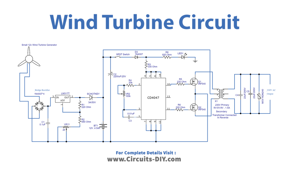
Circuit Diagram
Working Explanation
Five steps make up this small wind turbine for home:
- 12V Wind turbine generator/Bridge Rectifier Circuit
- Regulator / Battery charger circuit
- Inverter circuit using IC CD4047
- MOSFET Drivers
- Output Stage
Let’s talk about all the stages one by one
12V Wind Turbine Generator/Bridge Rectifier Circuit
We are aware that a bridge rectifier turns an AC source into a Direct Current (DC) supply, and in this case, we utilized four 1N4007 diodes as bridge rectifier elements to convert wind turbine energy into a DC supply.
Regulator / Battery Charger Circuit
Here, a three-terminal positive voltage regulator with changeable settings named LM317 is utilized, and it has a current rating of more than 1.5A and an output voltage range of 1.25 V to 37 V. The 12/4.5Ah SLA Battery receives the regulator’s final output, which serves as the DC bias for the inverter circuit.
Inverter Circuit using IC CD4047
This switching pulse is produced by the monostable/astable multivibrator IC CD4047, which operates at low power and is offered in a 14-pin dual in-line package. At Pins 13 and 11, it gives a full oscillation output of F and a half oscillation at Pins 10 and Q, respectively. There is a 50% duty cycle on each output pin.
Mosfet Drivers
This inverter circuit’s switching drivers are IRF540 Mosfets. It has high working temperatures and quick switching capabilities.
Output Stage
In the output stage, which is the key part of wind turbine generators, transformer X1 is utilized in reverse. The output voltage from the wind turbine generator is directly supplied into the positive regulator circuit of the LM317, which is set to provide 12 volts, and a battery is linked to this bias using a Schottky diode.
Now When the SPST switch is turned ON, the CD4047 IC starts oscillating since it is connected and set up as an astable multivibrator. The secondary winding of the X1 transformer is driven by the output Q and Q’s, which are directly supplied into the switching power MOSFET IRF540. Here, the current flow happens for a certain duration but not for a specific duration. As a result, the primary winding coil and variable electromagnet-generated EMF provide alternating current output. According to the number of windings and switching frequency, output voltage and frequency vary.
Application and Uses
- To generate electricity
- Home automation system
Related posts:
 How to make YouTube Play Button - Electronics Projects
 How to Make a Water Level Indicator using CD4511 & 74147 IC
 Simple Metal Detector using CA3140 IC
 4x4x4 LED Cube Arduino Electronics Project
 How to make Automatic Night Light Sensor Project
 How to make Audio Level Indicator - VU meter using LM3914 IC