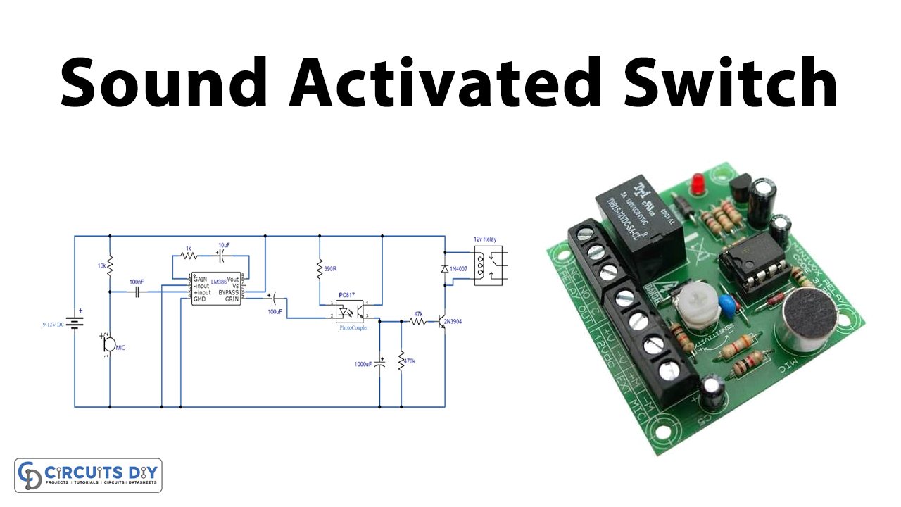
In this tutorial, we are going to demonstrate an easy and interesting DIY project that is a sound-activated switch. This circuit can activate a relay switch for a couple of minutes when any sound is received on the microphone. This circuit is great for students who want to make some interesting electronic projects since it is not complicated and one can make it easily in a short period of time.
You can find a lot of versions of this circuit with different specifications or modifications but in our project, we are making it using LM386 IC with a photocoupler at its output and a simple timer circuit built around a 2N3904 transistor.
Hardware Components
The following components are required to make Sound Activated Switch Circuit
| S.no | Components | Value | Qty |
|---|---|---|---|
| 1. | Transistor | 2N3904 | 1 |
| 2. | Diode | 1N4007 | 1 |
| 3. | Photocoupler | PC817 | 1 |
| 4. | IC | LM386 | 1 |
| 5. | Electret Microphone | – | 1 |
| 6. | Relay | 12V | 1 |
| 7. | Resistor | 10K, 47K, 470K, 390R, 1K | 1, 1, 1, 1, 1 |
| 8. | Ceramic Capacitor | 100nF | 1 |
| 9. | Electrolytic Capacitor | 1000µF, 100µF, 10µF | 1, 1, 1 |
| 10. | DC Supply | 9 – 12V | 1 |
LM386 Pinout
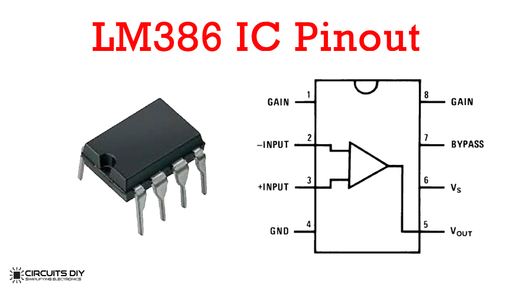
For a detailed description of pinout, dimension features, and specifications download the datasheet of LM386
PC817 Pinout
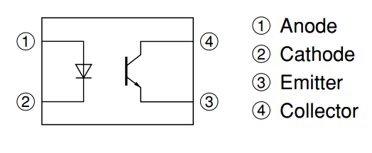
For a detailed description of pinout, dimension features, and specifications download the datasheet of PC817
Sound Activated Switch Circuit
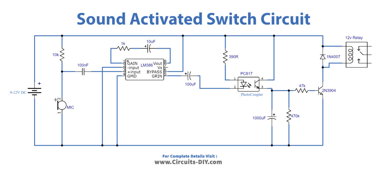
Working Explanation
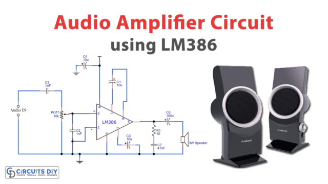
This circuit is operating on 9-12V DC. The working of this circuit is quite simple, the main component is an audio amplifier LM386 IC. Following are the steps that you should follow to make this circuit work,
- Sound is received by an Electret mic which converts these sound signals into electrical signals.
- These signals are fed to the input pin (pin2) of the IC which amplifies these signals.
- Now, these amplified signals are filtered through a 100µF capacitor used at the output pin of the IC (pin 5).
- These filtered signals go into the photocoupler, the output of the photocoupler charges the 1000µF capacitor next to it and also activates the transistor which eventually switches the relay ON.
- Both the transistor and relay stay activated until the 1000µF capacitor discharges; their activation time can be increased by increasing the value of the capacitor.
Applications and Uses
- Sound-activated bedside lamps
- Home Automation
- Sound-triggered recording systems
- Audio-activated relay switch