Introduction:
As we know, most digital or logic circuits need a square pulse as a carrier or clock signal externally, for this purpose square pulse generators are used. The square wave pulse generator is a kind of oscillator circuit that produces oscillations at the output only by receiving an impulse input which is also called a zero input. It is just like a Schmitt trigger circuit in which the output voltage decides the reference voltage for the comparator. These oscillator generators are used mainly in digital signal processing. The relaxation oscillator is the suitable one to generate square-wave oscillations.
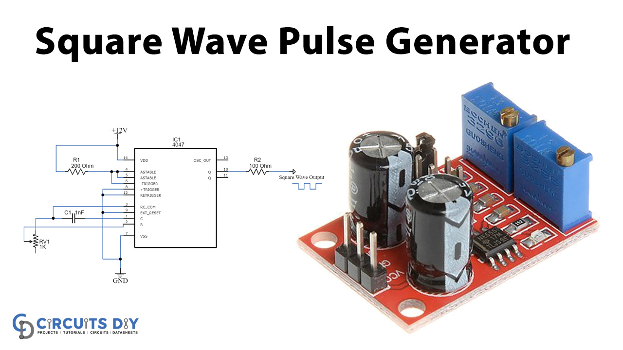
Here, we have built a square wave generator using an IC 4047 which is a low-power inverter, it can be operated in two modes that are astable or monostable. The IC is used to generate pulses like a square wave, sine wave, clock pulse, etc. The circuit diagram and its working explanation are given below in detail.
Hardware Components
The following components are required to make Pulse Generator Circuit
| S.no | Component | Value | Qty |
|---|---|---|---|
| 1. | IC | CD4047 | 1 |
| 2. | Variable Resistor | 1KΩ | 1 |
| 3. | Resistor | 200Ω, 100Ω | 1 |
| 4. | Ceramic Capacitor | 1nF | 1 |
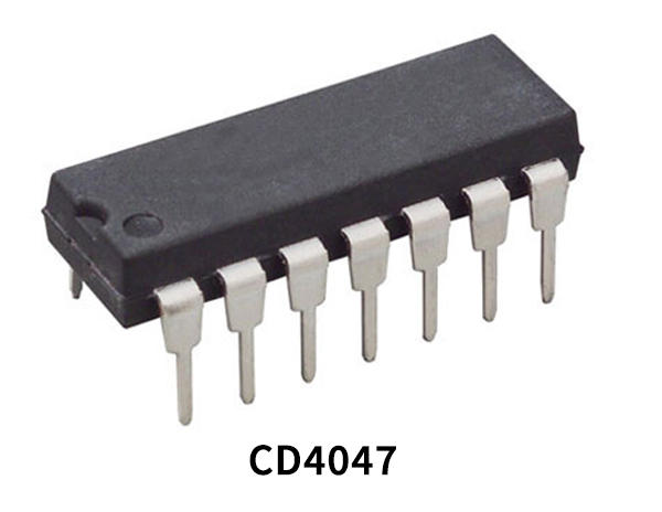
CD4047 Pinout
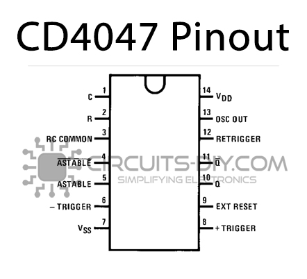
For a detailed description of pinout, dimension features, and specifications download the datasheet of CD4047
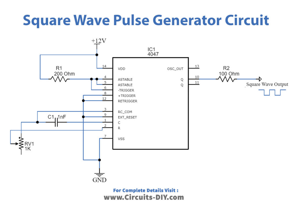
Pulse Generator Circuit
Working Explanation
IC 4047: It is a low-power inverter IC that uses 14 pins to process output, a resistor and a capacitor are also known as timing resistors and a timing capacitor is essential to generate a pulse. The IC produces a calculated pulse by controlling the frequency, output mode, and pulse position. Refer to the datasheet of IC4047.

The figure shows the IC 4047, which is a 14-pin monostable or astable multivibrator. It can take up to 15V bias voltage as input and output peak to peak pulse.
The 12 power supply is applied to the circuit, and the output is achieved from the IC terminal Q or Q´ gives the direst pulse and inverted pulse respectively. The amplitude of the output is controlled by the external resistor connected to the output terminal.
The shown network of resistor and capacitor generates sine wave output at the end and by changing the values, the amplitude of the sine wave is varied. The frequency is dependent on the output square pulse of the IC.
Sine wave output:

Applications:
Square wave generators find their uses in the following ways:
- It can be used for audio and radio systems.
- It is applicable in DSP systems to generate clocks for the microprocessors.
- It is also used in pulse width control systems.
- Furthermore, it is beneficial for different analog systems be it simple lamps or complex control systems.