Introduction
To adjust the audio signals during the recording, or to control the bass response of the speakers and headphones while listening, the systems and the devices used a tone control circuit. it’s a circuit that contains the amplifiers and filters in it. The filters filter out the signal. While amplifiers modify the signals before it is given to the devices like earphones and loudspeakers. Certainly, the passive tone control circuit is the circuit that doesn’t expect any additional supply. Hence, it’s cost-effective. Also, it only uses passive components like resistors and capacitors.
Working Principle of Passive Tone Control
The circuit of passive tone control comprises numerous capacitors. These capacitors change the sound by raising or lowering the frequencies that are in cut-off mode. In short, it reduces the full range signals and stimulates the lower and higher sound signals.
Hardware Required
| S.no | Component | Value | Qty |
|---|---|---|---|
| 1. | PCB Board | – | 1 |
| 2. | Quad Op-amp IC | TL072 | 1 |
| 3. | Capacitor | 1uf, 2uf 100pf, 2.2nf, 22nf, 220nf | 1, 1, 1, 1, 2, 1 |
| 4. | Resistor | 1K,100K, 10K, 2.2M | 2, 2, 2, 1 |
| 5. | Potentiometer | 100K | 4 |
| 6. | power supply | 15V | 1 |
Circuit Diagram
Working Explanation
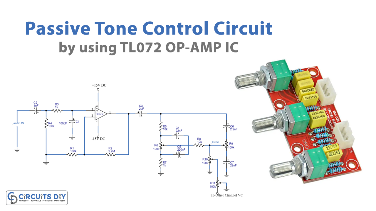
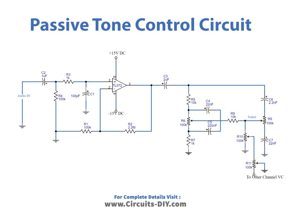
The passive tone control circuit comprises two stages. The first stage is the preamplifier stage, which includes the non-inverting IC TL072. It owns the capacitor C2 to decouple the input signal. Resistor R2 assists as the feedback resistor. While R1 is used to set the gain. The second stage of the tone circuit includes the potentiometer R6 to control the bass signals. R9 is to control the treble. While R8 provides the isolation between treble and bass signals. potentiometer R11 set the balance. And, R10 controls the volume and drives the load.
Application and Uses
- In hearing equipment
- To compensate for hearing deficiencies.
- In playback devices.
- for room acoustics.
Related posts:
 Class-A Headphone Amplifier Circuit Using Transistors
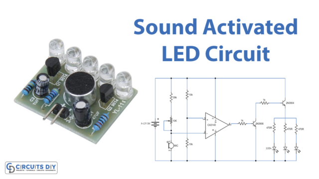 Sound Activated LEDs Using CA3140 IC
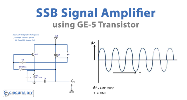 Single Sideband Suppressed Carrier (SSB) Signal Amplifier
 Bike Car Turning Signal Indicator Circuit using 555 Timer IC
 3 Circuits Of Guitar Fuzz Box & Fader Control
 20 Watts TDA2005 Bridge Amplifier with Tone Control