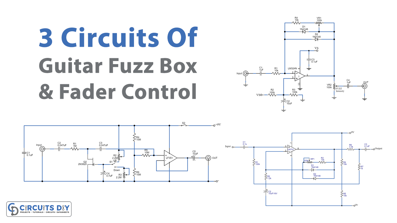
Introduction
Do you know about guitars? right, and you might have also played it, or maybe you are the one who knows everything about that particular instrument. And, you are also the one who loves electronics. So, let’s combine your love of instruments with electronics. Because, in this tutorial, we are going to make “3 circuits of guitar fuzz box and fader control”.
1. Simple Guitar Fuzz Box Circuit
This system allows you to manage or control the sound signal to make it as loud or as soft as you desire. A fuzzbox is just a miniature amplifier that is meant to be overdriven. Every amplifier has some amount of headroom. The waveform of the signal will be clipped if it exceeds the headroom. The sound will alter if the waveform’s shape is distorted. Suppose we begin with a smooth waveform and cut it. Clipping is not always all or nothing: there have been hard clipping and soft clipping. Before entering hard clipping, the amplifier begins to smooth off the edges of waveforms. in soft clipping. a warmer, more pleasing sound is produced.
Hardware Required
| S.no | Component | Value | Qty |
|---|---|---|---|
| 1. | IC | LM741 | 1 |
| 2. | Resistor | 10K, 100K, 1.2K, 1K, 3.3K | 3, 1, 1, 1, 1 |
| 3. | Capacitor | 0.1uF, 10uF | 2, 1 |
| 4. | Variable Resistor | 100k | 1 |
| 5. | Diode | 1N4148 | 2 |
Circuit Diagram
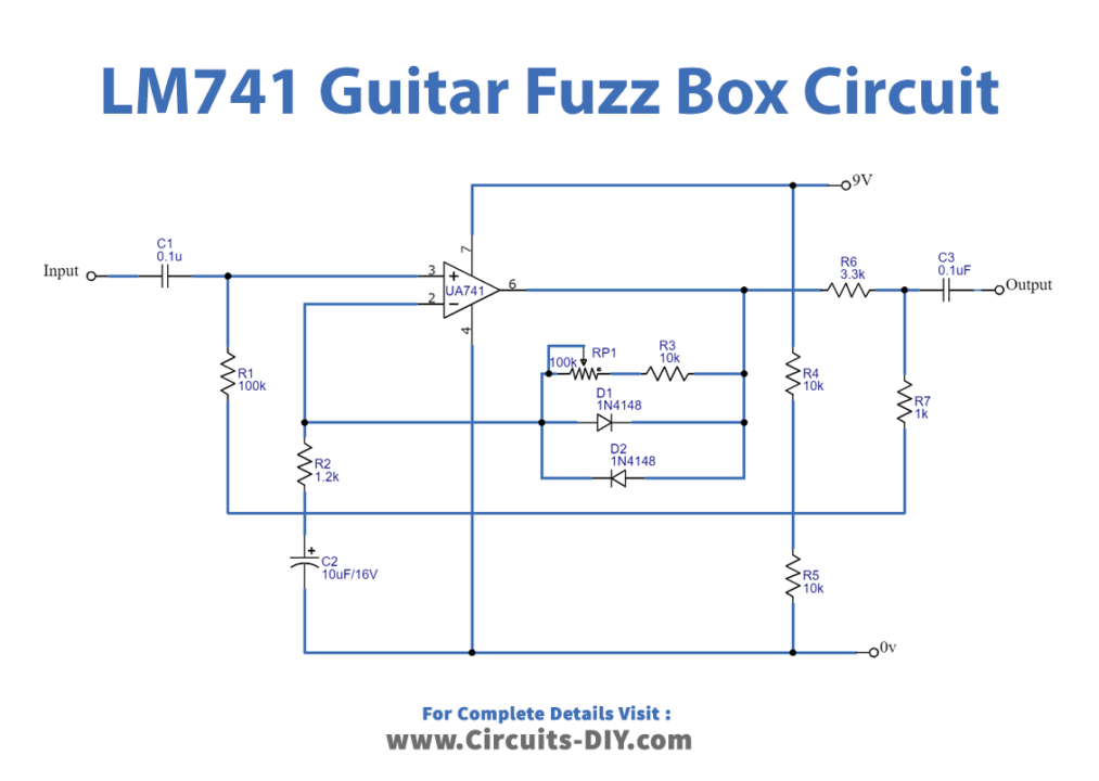
Working Explanation
This Guitar Fuzz Box uses IC-741 opamp. Normally used as a dual power supply. The input signal is sent through capacitor C1 to pin 3 of IC1. This gain is equivalent to the value of (VR1+R2+R3)/R2. And the gain depends on how you set the potentiometer VR1. The output voltage, though, is less than 600 mV. Since both diodes, D1 and D2 are connected in the feedback circuit. Resistors R6 and R7 are there to connect a signal attenuation circuit. As a result, the signal from the IC is just 150mV.
2. Fuzz Pedal Schematic
These are distortion pedals, but the sound is unique. Fuzz pedals generate a harmonically rich tone. The sound of fuzz pedals is similar to that of malfunctioning amplifiers, which allow sounds to sustain for longer periods.
Hardware Required
| Sr No: | Components | Qty |
|---|---|---|
| 1 | IC (LM324) | 1 |
| 2 | Resistor (10K, 100K) | 2, 2 |
| 3 | Capacitor (1uf, 0.1uF, 10uF) | 2, 1, 1 |
| 4 | Variable Resistor (100k) | 2 |
| 5 | Diode (1N4148) | 2 |
Circuit Diagram
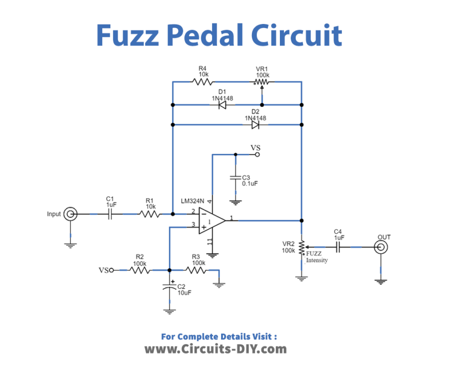
Working Explanation
The above diagram is the Fuzz pedal schematic, which is an audio converter circuit with fuzz. It employs two diodes working as the feedback circuit of the IC, LM324. This can also produce a musical tone with peculiar features. It will also restrict the output voltage and provide a 0.7Vp-p wave square signal.
3. Signal Automatic Fader using LF351
Hardware Required
| Sr No: | Components | Qty |
|---|---|---|
| 1 | IC (LF351) | 1 |
| 2 | Resistor (1M, 10M) | 1, 2 |
| 3 | Capacitor ( 0.1uf, 0.047uF, 4.7uf 10uF ) | 1, 2, 1, 1 |
| 4 | Variable Resistor (2.2M) | 2 |
| 5 | Diode (2N3820) | 1 |
| 6 | Switches | 2 |
Circuit Diagram

Working Explanation
The FET serves as a preamplifier in this Signal Automatic Fader circuit. The circuit now includes a high-frequency op-amp in a low-noise FET model, LF351. The switch S1 is used to modify the pitch to High or Low, and the potentiometers VR1 and VR2 are used to decorate the pitch.