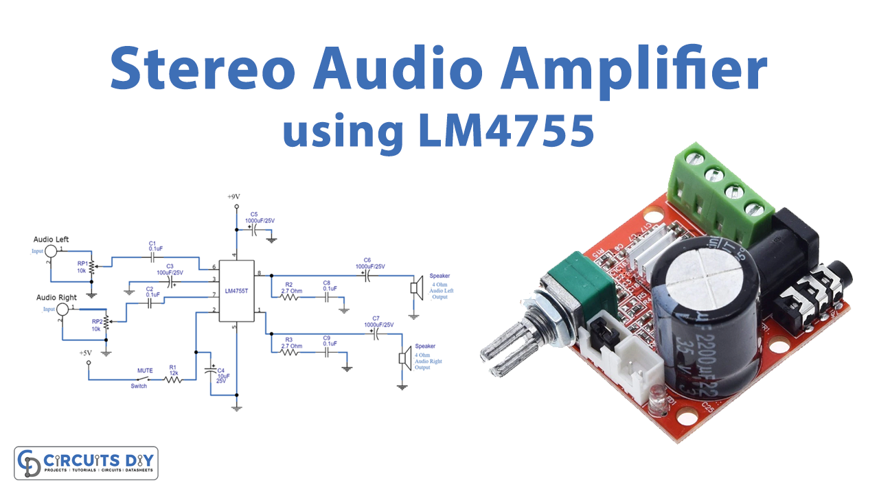
In this tutorial, we are going to make a “Stereo Audio Power Amplifier Circuit” using LM4755.
An audio power amplifier (or power amp) is an electronic amplifier that amplifies low-power electronic audio signals, such as the signal from a radio receiver or an electric guitar pickup, to a level that is high enough for driving loudspeakers or headphones. It is the final electronic stage in a typical audio playback chain before the signal is sent to the loudspeakers. As we need a lot of external components to construct stereo audio amplifiers but by choosing specific new integrated circuits, we can avoid those situations. Here we design a stereo audio power amplifier circuit by LM4755 IC with only a few external components.
The LM4755 is a stereo amplifier IC from texas instruments, it is capable of delivering 11W per channel of continuous average output power to a 4Ω load or 7W per channel into 8Ω by using a single 24V supply. This IC has a special integrated mute (The internal mute circuit and pre-set gain resistors provide a very economical design solution) function and it is designed to operate with a single supply range from 9V to 40V. This Integrated circuit has internal gain resistors, internal current limiting, and thermal protection. This stereo amplifier can be used in compact electronic products.
Hardware Required
| S.no | Component | Value | Qty |
|---|---|---|---|
| 1. | IC | LM4755 | 1 |
| 2. | Resistor | 12KΩ, 2.7Ω | 1,2 |
| 3. | Capacitor | 0.1uF, 100uF/25V, 10uF/25V, 1000uF/25V | 4,1,1,3 |
| 4. | Variable Resistor | 10KΩ | 2 |
| 5. | Speaker | 4Ω | 2 |
| 6. | Switch | – | 1 |
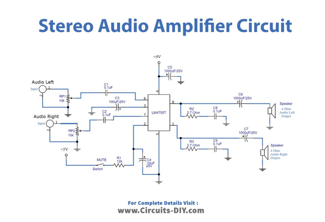
Circuit Diagram
Working Explanation
The main part of the circuit is LM4755 IC, it comes in a compact 9-lead TO-220 package, and can easily connect with a heat sink and printed circuit board. Audio left and right inputs are connected with LM4755 input pins through variable resistors VR1, VR2(limits the voltage level allowed to the amplifier’s input terminals) and coupling capacitors C1, and C2, which blocks DC voltage at the amplifier’s input terminals, and also creates a high pass filter with fc=1/ (2 • π • Rin • Cin)). Mute pin 2 is connected to a 5V supply with R1 and C4 capacitors, these elements provide mute function timing.
At the output side pin 1 delivers audio left output to 4Ω speaker through output coupling capacitor C6 and pin 8 delivers audio right output to 4Ω speaker through output coupling capacitor C7(C6 and C7 output AC coupling capacitor which blocks DC voltage at the amplifier’s output terminal. Creates a high pass filter with fc=1/ (2 • π • Rout • Cout)). At both outputs R2, R3 & C8, and C9 provide stabilization at the output stage from high-frequency oscillations. Here C3 provides filtering for the internally generated half-supply bias generator, and C5 provides power supply filtering and bypassing.
After completing the circuit wiring give stereo audio input at the input terminals and get a stereo output response. As we know that the circuit bias supply Vcc & speaker resistance can affect the output power, should have used a regulated power supply setup for better audio response. This circuit is designed for analog audio input and LM4755 IC is a class AB architecture amplifier, it provides typical 83KΩ input impedance, and 80dB mute attenuation in mute mode. These devices have limited built-in ESD protection. The leads should be shorted together or the device placed in conductive foam during storage or handling to prevent electrostatic damage to the MOS gates.
Applications
Can be used in stereos TVs, compact stereos, and mini component stereos.