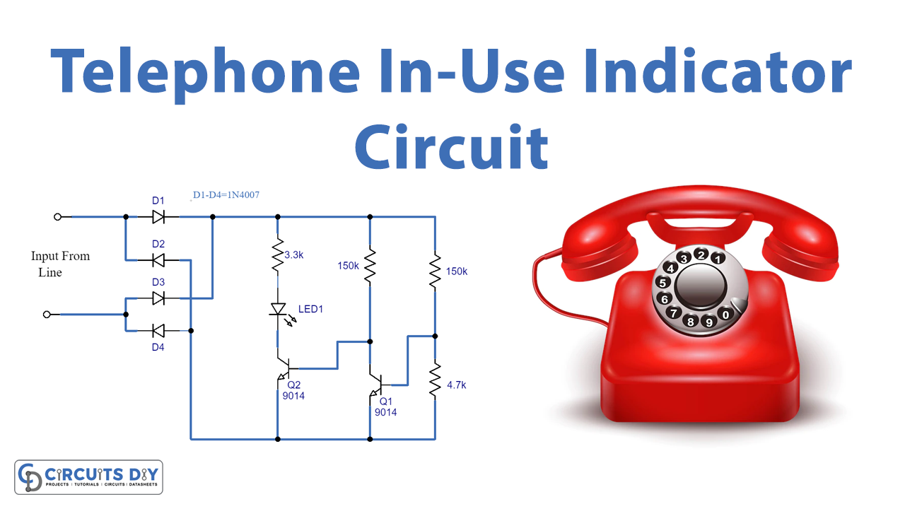
The telephone In-Use indicator is a simple circuit made using transistor 9014 and a diode bridge. It has an LED attached to it when a telephone is in use this LED glows.
Hardware Required
| S.no | Component | Value | Qty |
|---|---|---|---|
| 1. | Diode | 1N4007 | 4 |
| 2. | NPN Transistor | 9014 | 2 |
| 3. | Resistor | 3.3KΩ,4.7KΩ,150KΩ | 1,1,2 |
| 4. | LED | – | 1 |
| 5. | Telephone line | – | – |
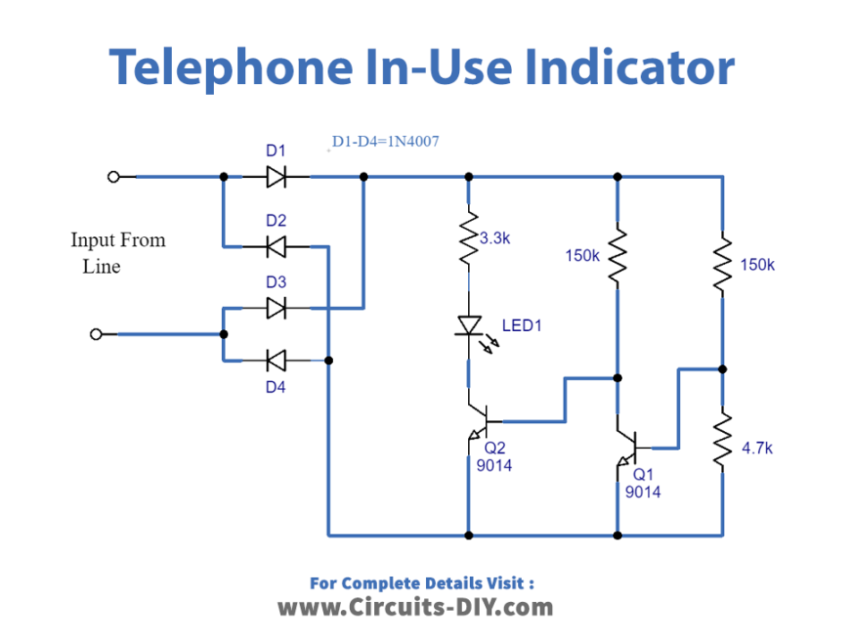
Circuit Diagram
Circuit Explanation
The telephone In-Use indicator circuit here is made using transistors and diodes. The phone line when busy or in use, the circuit indicates it by lighting the LED. Furthermore, the external power source is not required as the circuit draws power from the line. Next, the full bridge rectifier of 1N4007 converts the power drawn from the line into DC power. After that, the signal passes through the two transistors 9014 to get amplified. Hence, the LED lights up as soon as the amplified signal reaches it.
When the line is not in-use no power is there in the telephone line, thus, no signal is rectified. Hence, LED remains in OFF condition.
Application
Detection of telephone line tapping/misuse attempts.