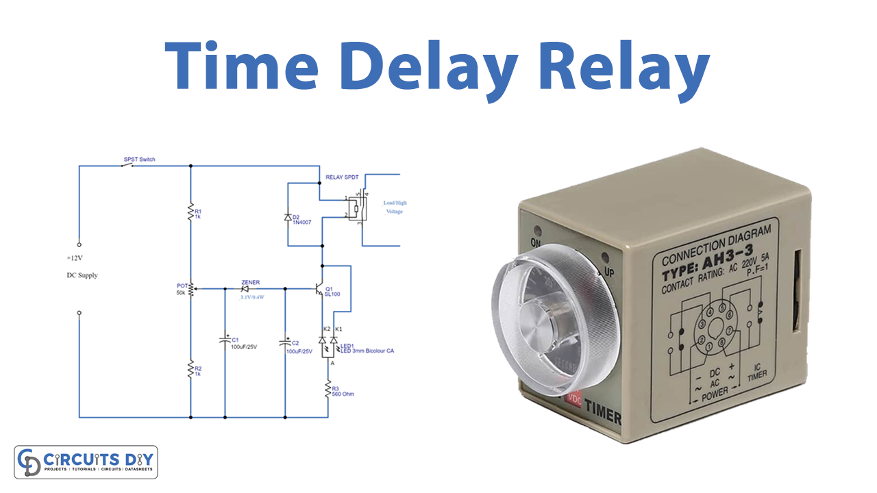
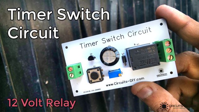
In this tutorial, we are going to make a “Time Delay Relay”. Time delay relays are simply controlled relays with a time delay function built in. They control an event by energizing the secondary circuit, after a certain amount of time or for a certain amount of time (some can even do both).
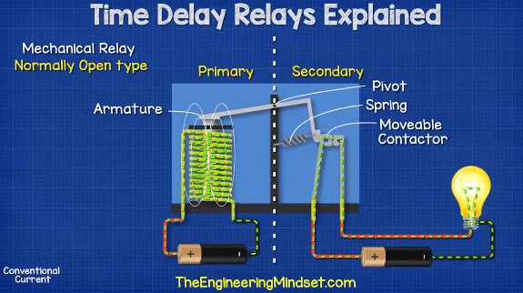
In a standard normally open control relay, the contacts on the secondary side close immediately when voltage is applied to the coil on the primary side. When the electricity is cut on the primary side, the contacts on the secondary side will open and cut the power to the load.
For some applications we do not want an immediate response on the secondary side, we want this to occur after a certain amount of time or only for a certain duration. For this, we can use a time delay relay. Here we design a simple time delay relay circuit as some electrical/electronic projects need supply after some time delay or need to cut the supply after some delay, for that purpose we can use this simple circuit.
Hardware Required
| S.no | Component | Value | Qty |
|---|---|---|---|
| 1. | SPDT Relay | – | 1 |
| 2. | Zener Diode | 3.1V/0.5W | 1 |
| 3. | Transistor | SL100 | 1 |
| 4. | LED BICOLOR | – | 1 |
| 5. | Diode | 1N4007 | 1 |
| 6. | SPST Switch | – | 1 |
| 7. | Resistor | 1KΩ,560Ω | 1,1 |
| 8. | Capacitor | 1000uf/25V,100uf/25V | 1,1 |
| 9. | Potentiometer | 50KΩ | 1 |
| 10. | Connecting Wires | – | – |
| 11. | Battery | 12V | 1 |
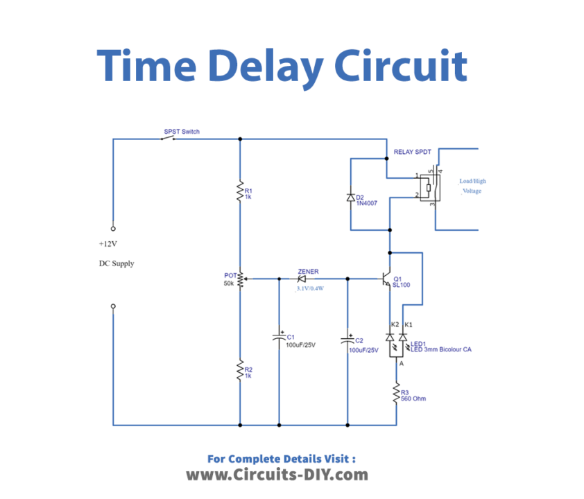
Circuit Diagram
Working Explanation
This time delay relay circuit contains an electromechanical relay and driver circuit. This circuit decides the time delay, to give power supply to the electromechanical relay coil (by the way to the load connected to the relay).
Here the first stage of this circuit is time delay elements, such as voltage divider resistor series and two electrolytic capacitors. Resistor R1, potentiometer, and R2 are connected in series, and across to the DC input supply. The output of the variable resistor (potentiometer) is connected to the C1 capacitor and reverse-biased Zener diode, then the C2 capacitor finally to the base of transistor SL100. The second stage of this circuit is a relay with an indicator LED. Here 12V relay is connected with the collector terminal of the SL100 transistor, the bicolor LED terminal green is connected with the emitter of Q1 and terminal red is connected across the collector.
Now we need to power the circuit, here supply value to this circuit depends on the value of the potentiometer. A small level of voltage is passed to C1, and it gets charged. When it’s completed and above the cutoff limit of the Zener diode, voltage is passed to the C2 capacitor and it gets charged. Then the base-emitter voltage limit of the Q1 transistor is reached by the C2, Q1 gets turned ON and the relay coil gets a complete DC supply. To complete the above process it takes some time delay depending on potentiometer value, C1-C2 charge time, and Zener diode breakdown voltage. Hence we can achieve a few seconds to a few minutes time delay. By changing the potentiometer value or C1-C2 value, we can achieve different time delay levels.
Application
We can use this circuit to turn ON/OFF some sensitive time delay required electrical applications such as.
- Flashing light control (time on, time off)
- Engine auto start control
- Furnace safety purge control
- Motor soft-start delay control
- Conveyor belt sequence delay