Switched mode power supply uses a switching regulator to convert electric power efficiently. SMPS transfers electric power from a source (AC mains) to the load by converting the characteristics of current and voltage. It always provides a well-regulated power to the load, irrespective of the input variations. SMPS incorporates a pass transistor that switches very fast typically at 50Hz and 1 MHz, between the ON and OFF states to minimize energy waste.
It can regulate the output power by varying the ON to OFF time, using minimum voltage so that efficiency is very high compared to the linear power supply. When we want to use SMPS for our projects, we can get good results due to stabilized constant current bias. But the cost and size of SMPS may be more huge than our project’s prototype. Here we can get rid of this problem by choosing compact SMPS modules, HiLink makes compact power modules under 3W and 5W categories.
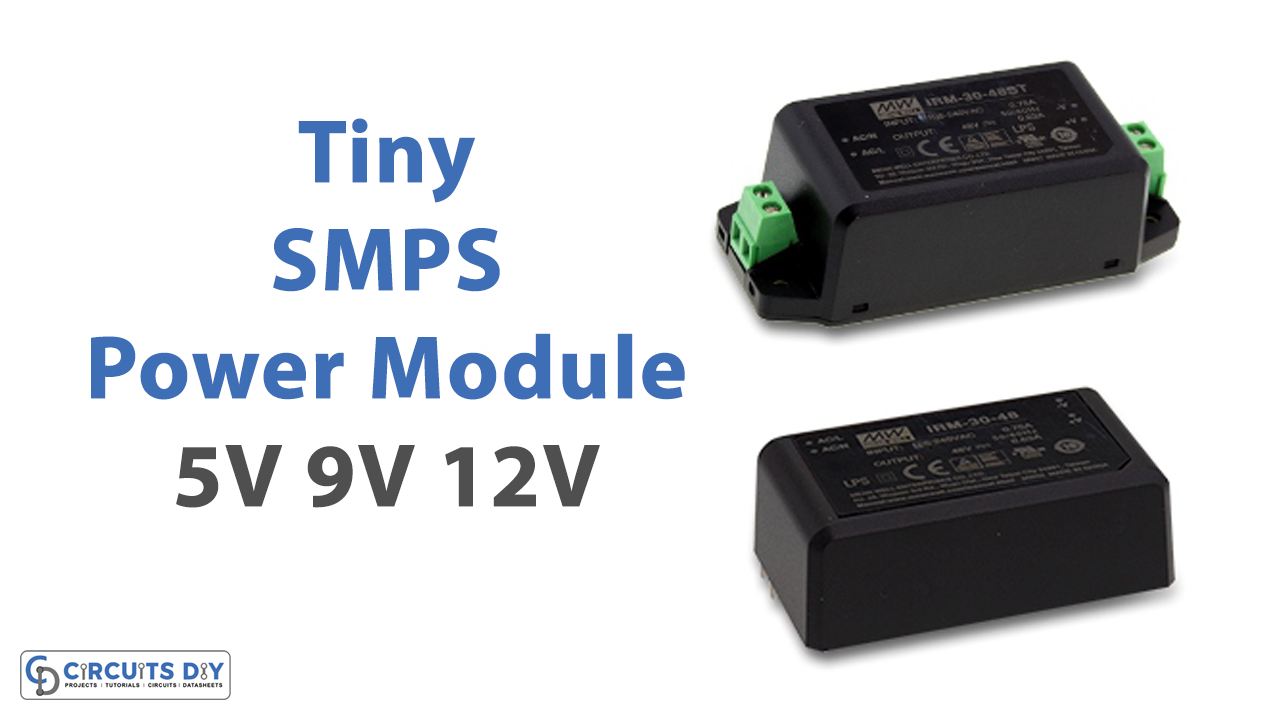
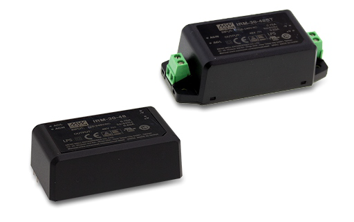
5V & 12V SMPS Module

As we know, these modules are PCB mount plastic enclosed isolated switching step-down power supply modules. They can take 100 to 240 Vac with 50-60 Hz frequency as input power supply, and give constant DC (5V or 12V depending on the module). These modules occupy a very tiny space on board, a size of a 5V module is 33 * 19 * 15mm, and the size of a 12V module is 38 * 23 * 18 mm with a weight of 20gm to 35gm respectively. It includes a way better power effectiveness ordinarily 60 to 70 percent, features a solid against interference, and has a wide yield range.
It is a low-cost power supply design because these modules have a built-in step-down transformer, rectifier, regulator, and filter. It provides high-efficiency output, high reliability, low-temperature rise, and high-security isolation. The AC input from mains is first rectified in the SMPS using a rectifier, to convert it into DC. Here the rectifier consists of a full wave diode bridge or module, that produces an unregulated DC voltage to the smoothing capacitor. Then the inverter converts the rectified DC into AC using a power oscillator. This power oscillator has a small output transformer with a few windings, at the frequency of 20-100 kHz. And switching is controlled by a MOSFET amplifier. As we know, for safety reasons the output AC voltage is usually isolated optically from the input AC by using an Optocoupler IC. Now the voltage converter, this stage has a high-frequency transformer. Here the inverted AC drives the transformer’s primary windings, which creates the up and down voltage at the output. The rectified output DC is filtered by using the filter section, which consists of inductors and capacitors. Some non-isolated SMPS contains an inductor instead of the transformer, and the circuit act as a boost converter or buck converter. In high-voltage SMPS, the capacitor-diode multiplier is used instead of inductors or transformers. By using a feedback system, the output voltage is compared with a reference voltage.
Hi-Link Compact SMPS module Product Page
Applications
These modules are capable to give good bias to a microcontroller or embedded electronics projects.