Introduction
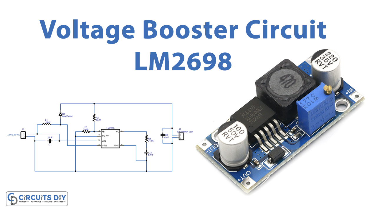
To increase the input voltage at the output load, the circuit commonly known as voltage booster is used. As the name implies, it takes the input voltage and with the help of some components transforms that voltage into high voltage. The circuit can be made using different methods like inductors, capacitors, semiconductor switches, etc. But, for efficient output, some voltage regulator ICs are also available in the electronic market. Hence, we will use one of them in our project. Therefore, in this tutorial, we are going to make a “Voltage Booster Circuit” using LM2698 IC. The IC turns on on minimum of 2.2 V and can tolerate a maximum of 12V.
Hardware Required
| S.no | Component | Value | Qty |
|---|---|---|---|
| 1. | IC | LM2698 | 1 |
| 2. | Inductor | 10µH | 1 |
| 3. | Diode | 0MQ040N | 1 |
| 4. | Capacitor | 4.7nF, 22µF, 10µF | 1, 1, 1 |
| 5. | Resistor | 3.48K, 30.1K, 24.9K | 1, 1, 1 |
| 6. | 2-Pin Connector | – | 2 |
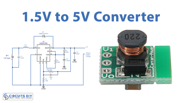
Circuit Diagram
Working Explanation
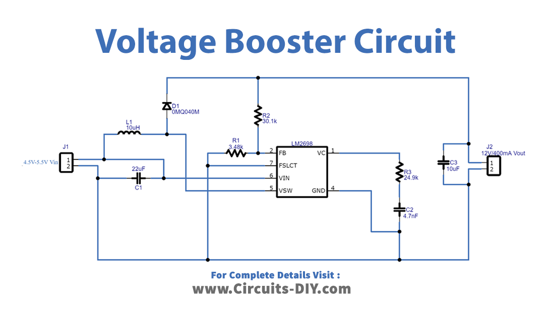
This voltage booster circuit includes the 8 pins IC. Input voltage is provided at pin 6 of an IC while pin 4 is used for ground. Pin 5 is the analog power switch input. Pin 1 is for the compensation network connection. Thus, wired to the output of the voltage error amplifier. Pin 2 is the input for the output voltage feedback. After these connections have been made, provide the input voltage in the range from 4.5V to 5.5V, and the circuit would convert this into 12V at the output. You can connect any load that needs 12V and draws a maximum of 400mA of current.
Application and Uses
- It can be used as a boost converter.
- Also, in the distributed power supply.
- In any electronic circuits that need to convert 5 V to 12V