Introduction
In this tutorial, we are going to make the ” LTC3442 Buck-Boost Converter Circuit “. But before making the circuit let’s understand the buck and boost converter separately. To increase or decrease the voltage taken from the input Engineers and circuit designers have worked and managed to make two types of converter, the boost converter, and the buck converter. Boost converter transforms the lower voltage of fix supply into higher voltages of variable supply. On the other hand, the buck converter takes the higher fixed input voltage and converts that into lower variable DC voltage. A buck-boost converter circuit merges details of both a buck converter and a boost converter which we are going to discuss in this article.
Hardware Required
| S.no | Component | Value | Qty |
|---|---|---|---|
| 1. | IC | LTC3442 | 1 |
| 2. | Inductor | 4.7µH | 2 |
| 3. | Li-ion battery | 3.7V | 1 |
| 4. | Ceramic Capacitor | 0.01µF, 470pF, 220pF | 2, 1, 1 |
| 5. | Electrolytic Capacitor | 10µF, 22µF | 1, 1 |
| 6. | Resistor | 1M, 75K, 200K, 15K, 340K, 2.2K | 1, 1, 2, 1, 1, 1 |
| 7. | 2-Pin Connector | – | 2 |
Circuit Diagram
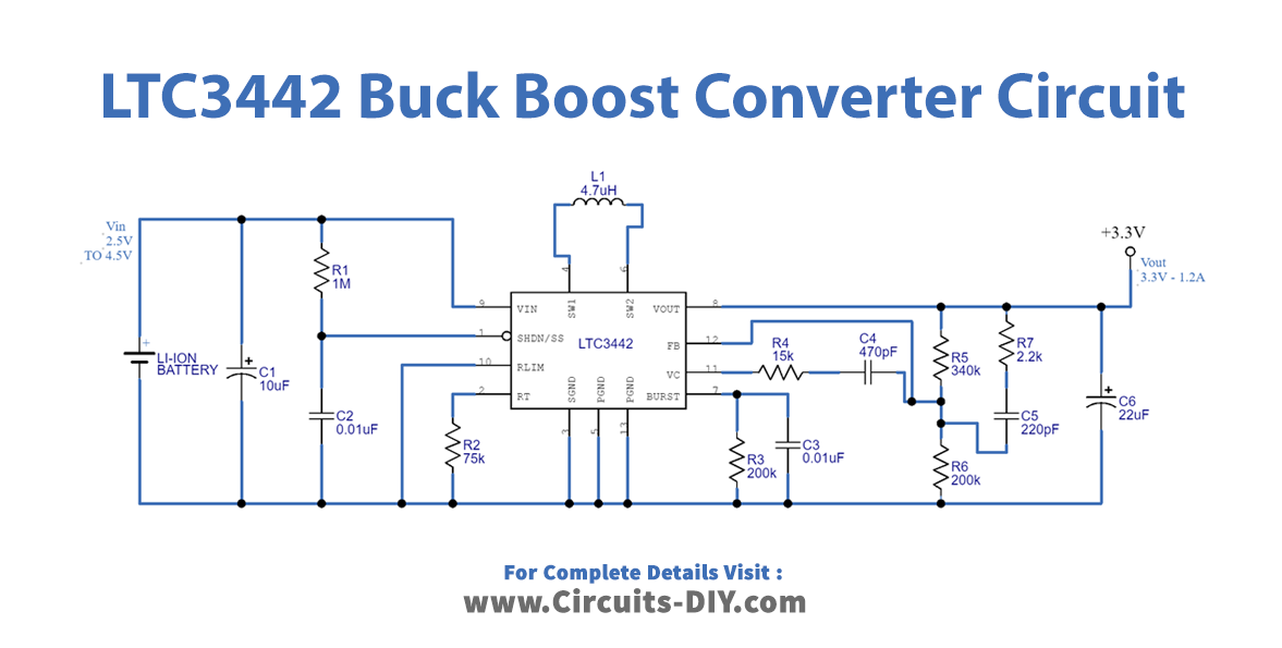
Working Explanation
This LTC3442 Buck-Boost Converter Circuit controls the output at 3.3V and adjusts it above or below the input voltage. The wired IC LTC3442 has four different automatic operations. Hence it also provides high-efficiency output. This buck-boost converter draws the shutdown current of fewer than 1micro amps and 35 microamps Quiescent current. when the input of 2.5V to 4.2V is given at the input pin 9 of an IC with several few components connected to their respective pins, it provides the output of 3.3V at pin 8. Hence this output can be varied above and below the 3.3V.
Application and Uses
- It can be used in battery power systems.
- It can also be utilized in adaptive control systems.
- Moreover, in regulated power supplies.
- It may also be utilized in power amplification.
- in consumer electronics.