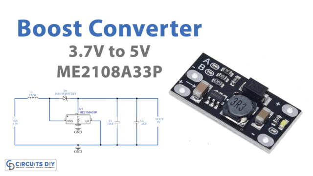
In this tutorial, we are going to make a “3.7V to 5V Boost Converter”.
As if every time in the circuit when we use a Microprocessor or low-power controllers, we need to provide additional power sources to drive external peripherals. When we implement more power sources then the circuit design becomes bulky and more complex. We can achieve it by boosting the converter. A boost converter is a DC-to-DC power converter that steps up voltage while stepping down current from its input supply to its output load. Boost converters are highly nonlinear systems and a wide variety of linear and nonlinear control techniques for achieving good voltage regulation with large load variations have been explored. We design a 3.7V to 5V boost converter circuit with DC/DC Step-up Converter ME2108 Series.
IC ME2108 is a step-up DC/DC converter with a low supply current, this IC reduces high frequency switching noise and output can be programmed between 2.0V to 7.0V. This IC can be used for battery-powered equipment with a low supply current. It requires only three external components to become a step-up converter.
Hardware Components
The following components are required to make the Boost Converter Circuit
| S.no | Component | Value | Qty |
|---|---|---|---|
| 1. | IC | ME2108A33P | 1 |
| 2. | Inductor | 22µH | 1 |
| 3. | Schottky diode | SS14 | 1 |
| 4. | Capacitor | 12µF | 2 |
| 5. | Connecting Wires | – | – |
| 6. | Power Supply | 3.7V | 1 |
ME2108A33P Pinout
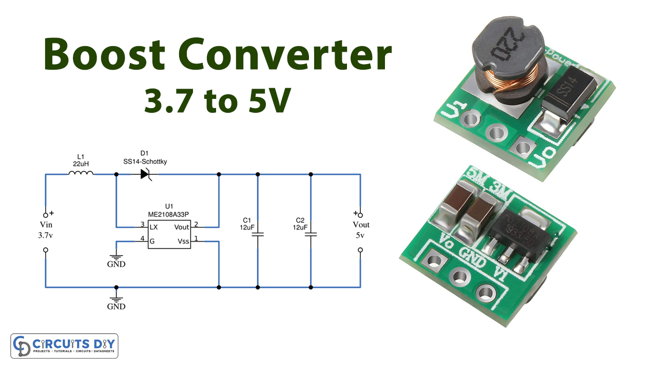
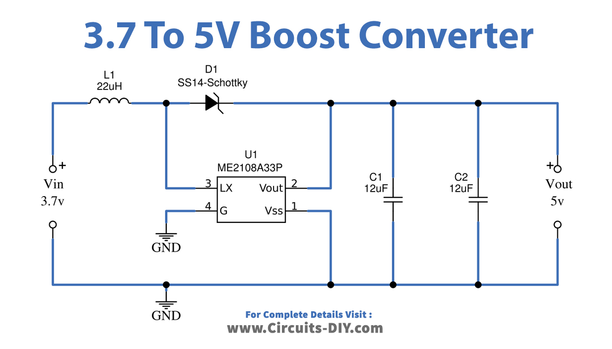
Boost Converter Circuit
3.7V to 5V Boost Converter Breakout Board
When you design the PCB for boost converter using ME2108 set external components close enough to the IC and minimize the connection between components and IC.
Use a 10µF value capacitor more in the 1210 package (you can try some other packages also). Use SMD Inductor 220 for better noiseless output. For a fast-switching response use SMD Schottky diode SS14.
Working Explanation
A 3.7V to 5V boost converter circuit is designed with DC/DC Step-up Converter ME2108 Series, IC ME2108 is a step-up DC/DC converter with a low supply current. As we know DC power supply can be boosted by a high-frequency switching pulse way this prototype schematic uses the same principle to bring high voltage output from a low voltage input. this IC ME2108 reduces high frequency switching noise and output can be programmed between 2.0V to 7.0V. Due to internal architecture, the IC ME2108 uses minimum external components.
It requires Inductor at the input and a Schottky diode then Capacitors at the output. This IC can deliver 400mA output current if the input voltage is 3.0V and the output voltage is fixed at 5.0V. It uses 180KHz maximum switching frequency by the value of Inductor and output capacitor we can change the output voltage range.
Applications
This includes the following applications.
- Hybrid electric circuits
- Solar power systems
- LED driver
- LED backlight and flashlight.