Introduction
Oftentimes, while building circuits, we find ourselves in a tricky circumstance where we require more power than the power source available. For instance, we only have 3V DC but want 9V or 12 V DC. The circuit known as the “boost converter” is used at this point. It assists in boosting the input DC voltage and delivering it to the output side, where it may be used by other devices that require higher voltage. “2.7V to 5V Boost Converter” is the topic of this article.
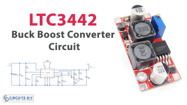
As we have already learned about the AC to DC converter, converting from lower to higher voltage is not difficult. However, the purpose of this circuit is to convert DC to DC. The circuit known as a voltage booster is used to raise the input voltage to the output load. It takes the input voltage and converts it to high voltage with the aid of several components. Inductors, capacitors, semiconductor switches, and other components can be used to create the circuit. However, several voltage regulator ICs are also accessible in the electronic market for efficient output. As a result, one of them will be used in our project. This circuit also employs the Schottky diode SS14 with the IC LTC3440.
Hardware Required
| S.no | Component | Value | Qty |
|---|---|---|---|
| 1. | IC | LTC3440 | 1 |
| 2. | Schottky Diode MBRM | 120T3 | 1 |
| 3. | Inductor | 10µH | 1 |
| 4. | Switch | – | 1 |
| 5. | Resistor | 1MΩ, 60.4KΩ, 15KΩ, 619KΩ, 200KΩ | 1, 1, 1, 1, 1 |
| 6. | Electrolytic Capacitor | 10µF, 22µF | 1, 1 |
| 7. | Ceramic Capacitor | 0.1µF, 1.5nF | 1, 1 |
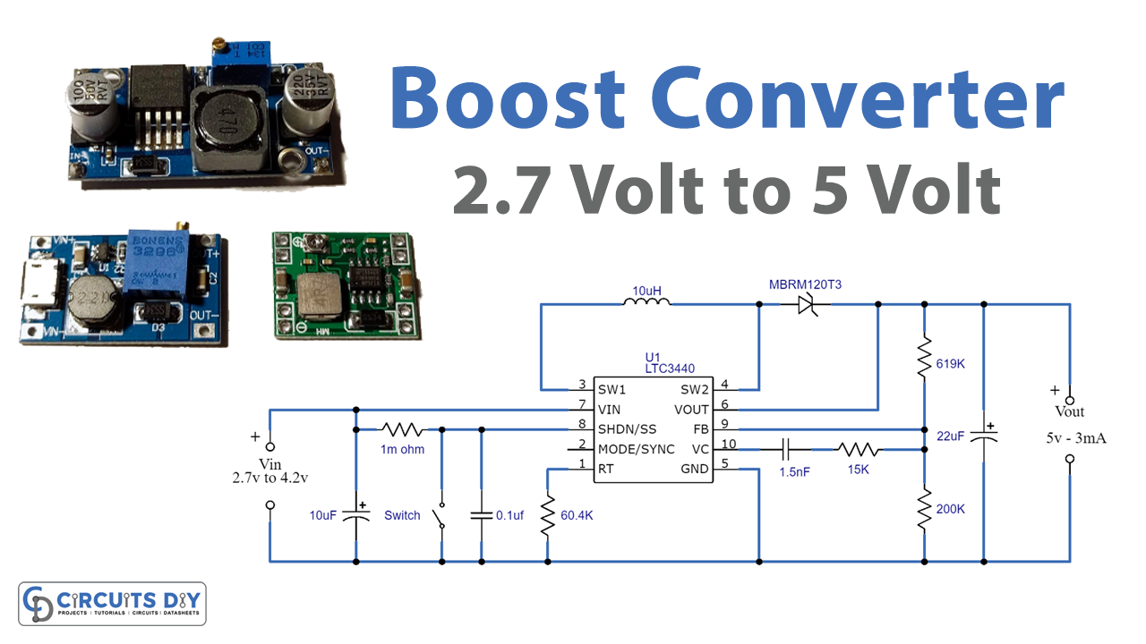
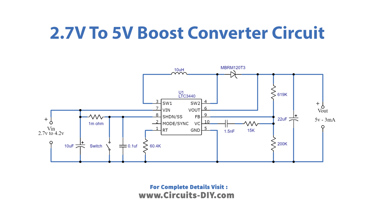
Circuit Diagram
Working Explanation
The 2.7 volt to 5 Volt boost converter employs a fixed frequency boost converter, the LTC3440 Buck-boost IC. The LTC3440 is a high-efficiency DC-to-DC converter that can work with input voltages that are lower, higher, or equal to the output voltage. The LTC3440 has a synchronous rectification efficiency of up to 96 percent and a maximum output current of 600 milliamperes. The IC has a built-in synchronizable oscillator with a frequency range of 300 kHz to 2 MHz that may be modified.
Inductors with high-frequency core material should be utilized to get high-efficiency outcomes. Resistor R2 sets the oscillator frequency, while the output is adjusted to 5 volts by resistors R4 and R5. The frequency compensation network is formed by resistor R3 and capacitor C3, with C3 serving as the input bypass capacitor. The output filter capacitor is C4 and the shutdown switch is S1.
Application and Uses
- Consumer electronic devices widely use boost converters.
- In battery power supplies, etc.
- Different electronic devices use this circuit.