Introduction
As the years are passing, the modern world is trying to get wire-free. Wireless gadgets and devices are not a new thing now. Wireless communication refers to the transfer of data over a long distance without the need for wires, cables, or other electrical conductors. Thus, wireless communication is a wide word that encompasses all methods and ways of communicating between two or more devices using wireless communication devices. A wireless switch is one of those devices. So, in this tutorial, we are going to make a “Wireless switch using 434MHz ASK modules”.
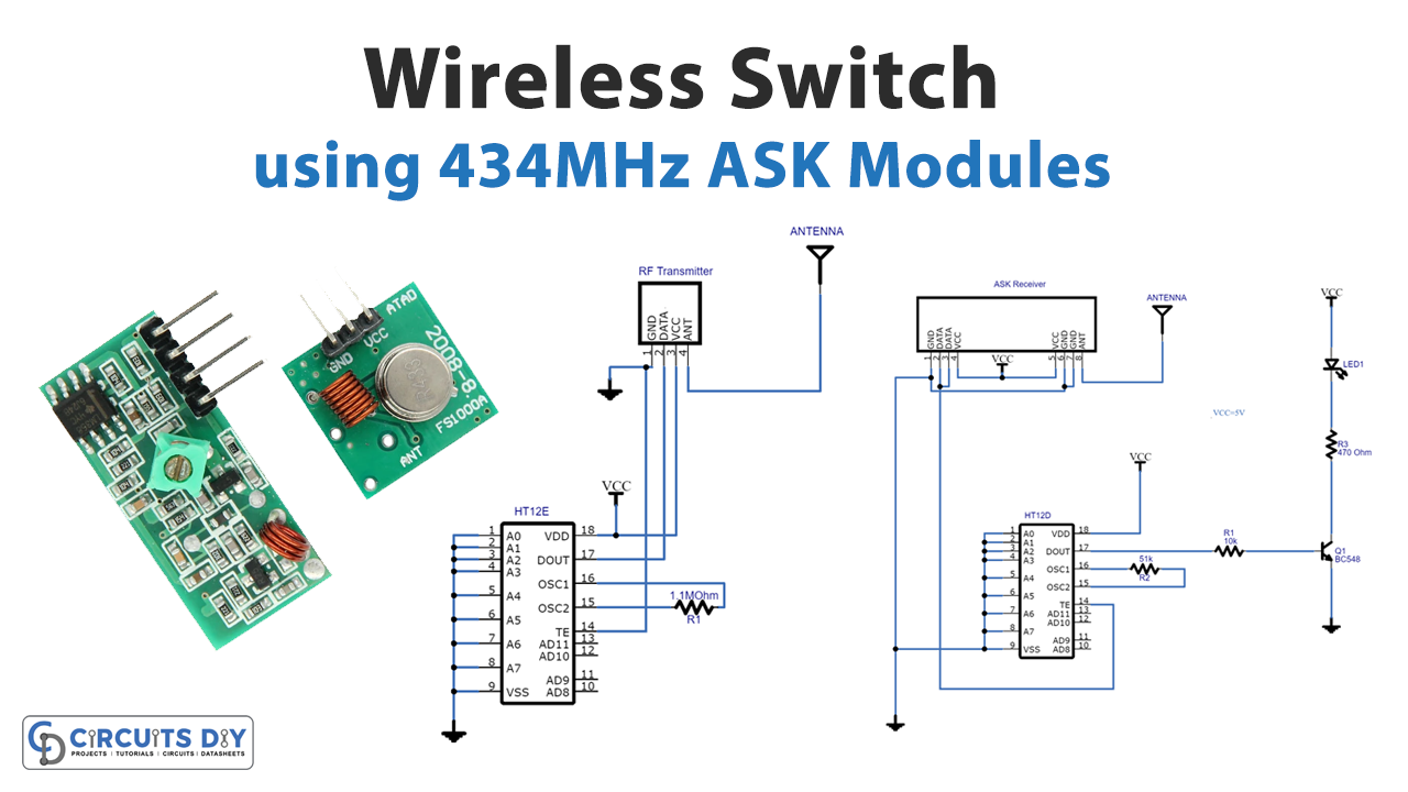
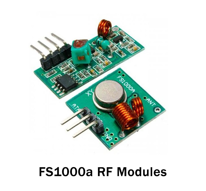
We used a 434MHz transmitter and receiver module to construct the circuit. For frequency stability, the ASK Hybrid transmitter module has a saw resonator. A PLL synthesizer and a crystal oscillator are included in the receiver. This transmitter and receiver are used to make remote controls using HT12E and HT12D ICs.
Hardware Components
The following components are required to make Wireless Switch Circuit
| S.no | Component | Value | Qty |
|---|---|---|---|
| 1. | Encoder IC | HT12E | 2 |
| 2. | Transmitter | ASK 434MHz | 1 |
| 3. | Receiver | ASK 434MHz | 1 |
| 4. | Antenna | – | 2 |
| 5. | NPN Transistor | BC548 | 1 |
| 6. | LED | – | 1 |
| 7. | Decoder IC | HT12D | 1 |
| 8. | Resistor | 10K, 51K, 1.1M, 470Ω | 1, 1, 1, 1 |
BC548 Pinout
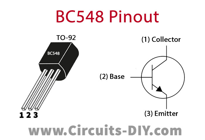
For a detailed description of pinout, dimension features, and specifications download the datasheet of BC548
Wireless Switch Circuit
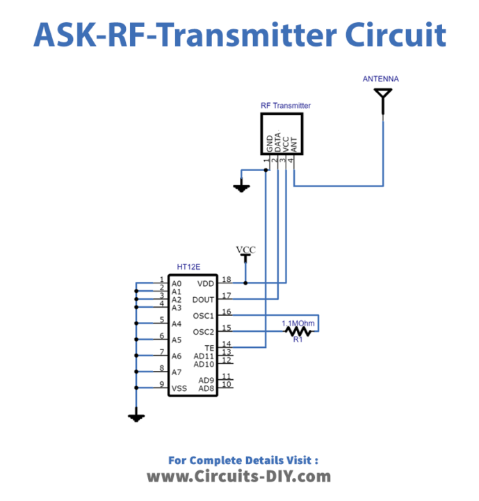
ASK Transmitter circuit
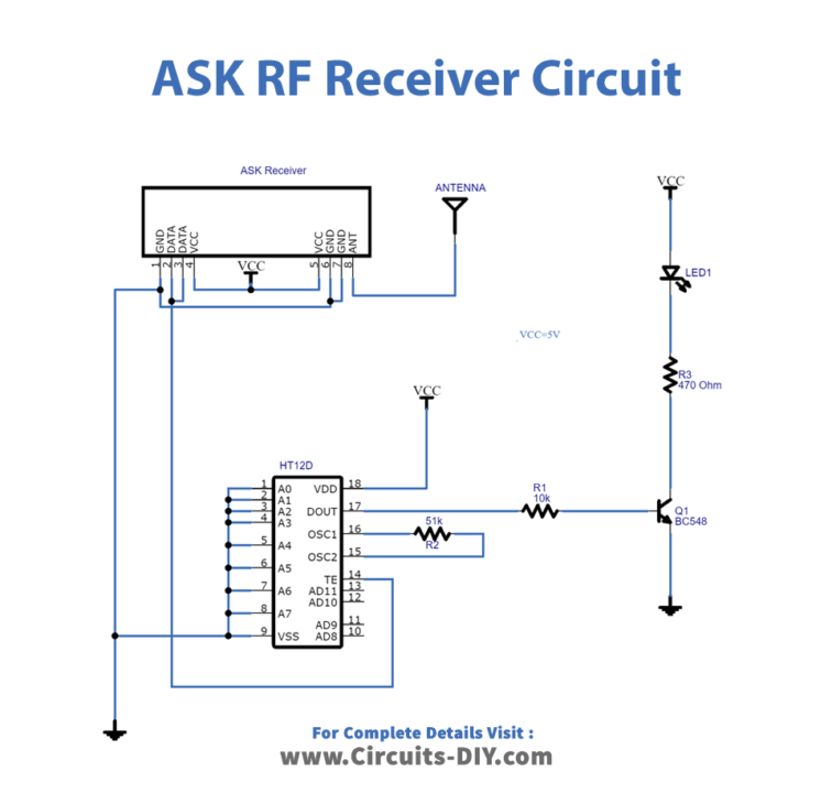
ASK Receiver circuit
Working Explanation
In this Wireless switch, to send and receive RF signals, we utilized a 434MHz Amplituude shift key (ASK) transmitter and receiver module. The encoder HT12E and decoder HT12D are also employed for the specific purpose of transmitting and receiving key data.
The encoder can encode N address bits and 12 data bits, each of which has two logic states. The identical decoder decodes the received signal from the ASK receiver and outputs the right logic state.
Application and Uses
- This circuit is excellent for designing a remote control utilizing the RF technique.