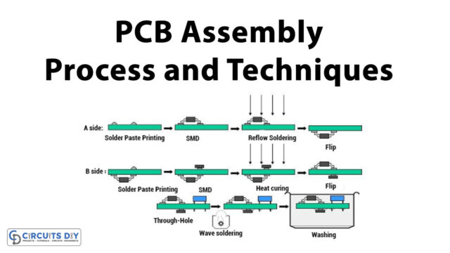
A printed circuit board (PCB) design brings your electronic circuits to life in the physical form. Using layout software, the PCB design process combines component placement and routing to define electrical connectivity on a manufactured circuit board. Printed circuit boards are very crucial in electronics circuit design and making, these PCB boards are acts as a support base for the electronic elements & components and provide bias and signal path to the required components. Nowadays growth of SMD (Surface Mount Device) and SMT (Surface Mount Technology) shrinks the size of the electronic component and makes it more complex for the PCB design. Due to no pinhole terminals in SMD components, two sides of the PCB board filled up with tracks and components. The Printed Circuit Board has copper tracks to connect the electronic components placed upon it, different types of PCBs are,
- Single Sided PCBs
- Double Sided PCBs
- Multilayer PCBs
- Rigid PCBs
- Flex PCBs
- Rigid-Flex PCBs
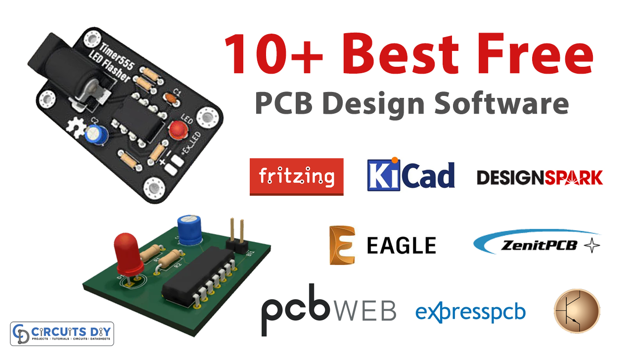
We need good PCB design software in order to produce compact, quality perfect printed circuit board. This article will help you to find the leading and competitive 10+ free PCB design software.
- eSim
- Kicad
- gEDA
- Free PCB
- Osmond PCB
- ExpressPCB
- PCBWeb Designer
- DesignSpark PCB
- Fritzing
- Eagle
- ZenitPCB
eSim

eSim (previously known as Oscad / FreeEDA) is an open-source EDA tool for circuit design, simulation, analysis, and PCB design. eSim offers similar capabilities and ease of use, as any equivalent proprietary software for schematic creation, simulation, and PCB design. Without having to pay a huge amount of money to procure licenses. It is an integrated tool built using free/libre and open-source software such as KiCad, Ngspice, Verilator, Makerchip, and GHDL. eSim is released under GPL. This software runs on Ubuntu Linux and Windows, it can be an affordable alternative for educational institutions and SMEs. It can serve as an alternative to commercially available/licensed software tools like OrCAD, Xpedition, and HSPICE.
Features of eSim
- Draw circuits using KiCad, create a netlist, and simulate using ngspice.
- Design PCB layouts and generate Gerber files using KiCad.
- Add/Edit device models (Spice Models) and subcircuits using the model builder and subcircuit builder tools.
- Perform Mixed-Signal Simulation.
- Support for Ubuntu and Windows OS.
Kicad

Kicad EDA is a cross-platform and open-source electronic design automation suite. It enables support for every aspect of electronics design, such as schematic capture. It includes all the tools you need for schematic design. Place symbols from KiCad’s included symbol library, and draw wires to make circuits. And manipulate your schematic drawing to make a final engineering design, to take into PCB. Electrical rules check, (ERC), automatically verifies your schematic connections. It checks for output pin conflicts, missing drivers, and unconnected pins. Exports netlists in formats, such as Pspice, Canstar, PcbNew, and “Generic” XML. KiCad comes bundled with a vast library of symbols, footprints, and matching 3D models. They are community maintained, so they never stop improving. It allows you to modify the aesthetic appearance of the board or to hide and show features for easier inspection (Kicad software). Import / migrate from other CAD tools, KiCad currently supports schematic designs from:
- EAGLE
- Altium Circuit Maker
- Altium Circuit Studio
- Altium Designer
- CADSTAR
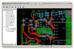
gEDA

PCB design software from gEDA is a cross-platform software and has rats nest features, schematic/netlist import, and design rule checking. And provides Industry standard RS-274X (Gerber), photorealistic design review images, and a lot more..(gEDA PCB software). The gEDA project has produced and continues working on a full GPL suite and toolkit of electronic design automation tools. These tools are used for electrical circuit design, schematic capture, simulation, prototyping, and production. Currently, the gEDA project offers a mature suite of free software applications for electronics design, including schematic capture, attribute management, bill of materials (BOM) generation, net listing into over 20 netlist formats, and analog and digital simulation, and printed circuit board (PCB) layout. The gEDA project was started because of the lack of free EDA tools for POSIX systems, with the primary purpose of advancing the state of free hardware or open-source hardware. The suite is mainly being developed on the GNU/Linux platform with some development effort, going into making sure the tools run on other platforms as well.
Free PCB
FreePCB is a PCB designer software for Microsoft Windows. It was designed to be easy to learn and easy to use, yet capable of professional-quality work. It does not have a built-in auto-router, but it can use the FreeRoute web-based auto router at www.freerouting.net. Some of its features are:
- Board size up to 60 inches by 60 inches
- Uses English or metric units (i.e. mils or mm) for most functions.
- Footprint libraries courtesy of Ivex Design International, PCB Matrix, and the IPC.
- Copper fill areas
- Footprint Wizard and Footprint Editor for creating or modifying footprints
- Imports and exports PADS-PCB netlists
- Exports extended Gerber files (RS274X) and Excellon drill files
- Design rule checker
- Autosave
These are notable features of built-in Freepcb PCB design software. (free PCB Software)
Osmond PCB
Osmond PCB is a tool for designing printed circuit boards. It can be used to design boards of any size and depth (layers), as it has multiple-layer design options. It supports circular, rectangular, and oval pads as well as variable trace widths and trace spacing. Routing can be manual or semi-automatic and includes automatic clearance checking. Dimensions can be given in imperial or metric units. Output options include Gerber, Excellon, and DXF.
We can design thru-hole and surface mount-based PCBs. It has design rule-checking features and produces industrial standard board output (Osmond PCB Software).
ExpressPCB

ExpressPCB software is a user-friendly easy-to-use PCB design software. Designing circuit boards is simple for the beginner and efficient for the professional. ExpressPCB is a CAD (computer-aided design) free program designed, to help you create layouts for printed circuit boards on your Windows PC.
And it provides well-explained documentation & steps on, how to make a printed circuit board (ExpressPCB software).
It is easy, even for first-time users. Here are the steps:
- Select the Components
- Position the Components
- Add the Traces
- Edit the Layout
- Order your PCBs
PCBWeb Designer

PCBweb is a free CAD application for designing and manufacturing electronics hardware, it provides full-service design and manufacturing features. We can do schematic capture fast using an easy-to-use writing tool, and we can create multi-layer boards. It has an integrated arrow part library (PCBweb designer). PCBWeb designer lies within photo & graphics tools, more precisely viewers & editors. The current installation package available for download occupies 21.3 MB on disk. This free program was originally produced by Silicon Frameworks, LLC.
DesignSpark PCB
DesignSpark PCB software from RS Components and Allied Electronics makes it easy to design complex PCBs, and this software works with minimum configuration systems. It is a completely free Windows software application for generating PCBs. It is fully compatible with the PICAXE Circuit Creator system. It has huge library collections and good support from forums and video tutorials (DesignSpark PCB). This software is free from practical constraints on board size, pin counts, layers, and output types, that can be used for schematic capture, PCB layout, and generating manufacturing files. Automatic placement and auto-routing are fully supported. Completed designs can be printed, and exported as an image or pdf file, and extended Gerber outputs allow the designer to choose who will manufacture their board (or to use a third-party tool such as CopperCAM for isolation routing). Bill of materials reports can also be generated at any time. DesignSpark PCB also supports the importing of Eagle design files and libraries. A comprehensive standard parts library is supplied, which can be amended, copied, and added to as required. Sophisticated new part creation wizards make it easy to design new parts from scratch or by using standard symbols and footprints. This software can be used for personal or commercial projects without any charge. It may also be installed on school/university networks without any cost or complicated paperwork.
Fritzing

Fritzing is an open-source hardware initiative, that makes electronics accessible as a creative material for anyone. We offer a software tool, a community website, and services in the spirit of processing and Arduino. Fostering a creative ecosystem, that allows users to document their prototypes, share them with others, teach electronics in a classroom, and layout and manufacture professional PCBs… from its website (Fritzing software). The software was created with inspiration from the Processing programming language and the Arduino microcontroller, allowing a designer, artist, researcher, or hobbyist to document their Arduino-based prototype and create a PCB layout for manufacturing. Fritzing can be seen as an electronic design automation (EDA) tool for non-engineers: the input metaphor is inspired by the environment of designers (the breadboard-based prototype), while the output is focused on accessible means of production. Fritzing has a code view option, where one can modify code and upload it directly to an Arduino device.
Eagle

Autodesk Eagle PCB design software is a powerful and easy-to-use tool for every engineer, and it is offered in the free version and also paid version. It has easy to use schematic editor, a powerful PCB layout, and ready-to-use part libraries. And this software is most suitable for complex PCB designs (eagle software). EAGLE contains a schematic editor, for designing circuit diagrams. schematics are stored in files. SCH extension, parts are defined in device libraries.LBR extension. Parts can be placed on many sheets and connected together through ports. The PCB layout editor stores board files with the extension.BRD. It allows back-annotation to the schematic and auto-routing to automatically connect traces, based on the connections defined in the schematic. EAGLE saves Gerber and PostScript layout files as well as Excellon and Sieb & Meyer drill files. These are standard file formats accepted by PCB fabrication companies, but given EAGLE’s typical user base of small design firms and hobbyists. Many PCB fabricators and assembly shops also accept EAGLE board files (with extension . BRD) directly, to export optimized production files and pick-and-place data themselves. EAGLE provides a multi-window graphical user interface and menu system, for editing, project management, and customizing the interface and design parameters. Multiple repeating commands can be combined into script files (with the file extension . SCR). It is also possible to explore design files utilizing an EAGLE-specific object-oriented programming language (with extension . ULP).
ZenitPCB
Zenit PCB software is an excellent tool to create professionally printed circuit boards, and it is easy to use CAD program, ZenitPCB Suite is directed to all those people who want to make printed circuit boards for a hobby, or to students and academics from universities or high schools. People who want to create their own PCB with a professional approach, particularly without having to pay for expensive licenses from its website (ZenitPCB software).
ZenitPCB Layout is an excellent tool to create a professionally printed circuit board (PCB). It is a flexible easy-to-use CAD program. Which allows you to realize your projects in a short time. Zenit PCB Layout is completely freeware for personal or semi-professional use, limited to 800 pins which are borderline between hobby and professional jobs. With ZenitPCB Layout is possible to create the project starting both from the schematic capture and by the layout itself. In the first instance, you can import a netlist (file ASCII containing electrical info) from different schematic capture ( Orcad®, Pads®, Multisim®, Protel®, Eagle®….), with all the components and the relative electrical connections (net). In the second instance, you can realize your project directly from the layout editor, importing components from the library, and connecting the pins directly with the cursor (auto ratlines). It is, therefore, possible to create a board without importing a netlist from Schematic capture. ZenitPCB Layout has all the needs to achieve a good printed circuit board.