Introduction
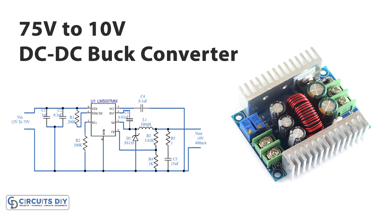
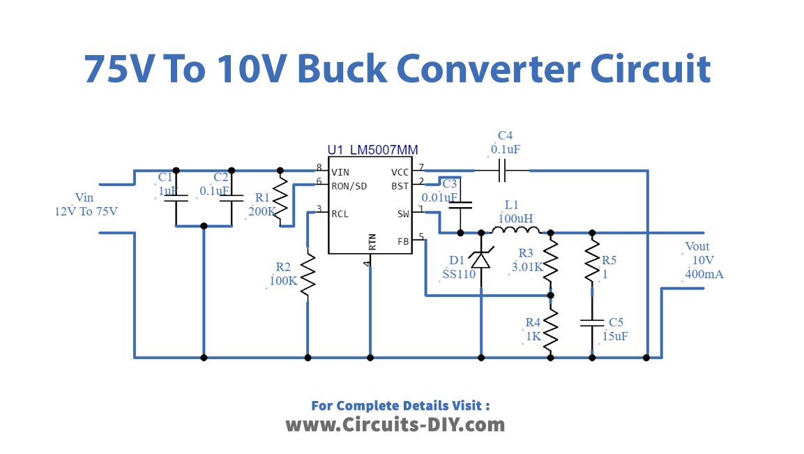
Suppose that you have a fixed DC power supply voltage, however, your device or circuit needs the variable voltage supply. What would you do at that time? To solve this, circuit designers have worked and made two types of converter, the boost converter, and the buck converter. Boost converter transforms the lower voltage of fix supply into higher voltages of variable supply. On the other hand, the buck converter takes the higher fixed input voltage and converts that into lower variable DC voltage. So, in this tutorial, we are going to create a “75V to 10V DC-DC Buck Converter Circuit” It uses the very low-cost and efficient buck regulator IC which requires some external yet affordable electronic components
Hardware Required
| S.no | Component | Value | Qty |
|---|---|---|---|
| 1. | IC | LM5007MM | 1 |
| 2. | SMD Schottky Diode | SS110 | 1 |
| 4. | Capacitor | 0.1µF, 0.01µF, 1µF, 15µF | 2, 1, 1, 1 |
| 5. | 2-Pin Connector | – | 2 |
| 6. | Inductor | 100µH | 1 |
| 7. | Resistor | 200KΩ, 100KΩ, 3.01KΩ, 1K, 1 ohm | 1, 1, 1, 1, 1 |
| 8. | 2-Pin Connector | – | 2 |
Circuit Diagram
Working Explanation
This 75V to 10V DC-DC Buck Converter Circuit uses the LM5007MM IC having 8 pins. Pin 8 is for the supply voltage. Further, Pin 1 is the power switching node that is connected to the output filter of the circuit. Pin two is the boost strap capacitor input, an external capacitor is connected between the pin and pin 2. Pin 5 is the feedback pin that is connected to the inverting input of the internal regulation comparator. After these connections, an output of 10V with 400mA of current would be available at the load.
Application and Uses
- It can be used in battery chargers.
- Also, can be utilized in solar chargers.
- In audio amplifiers.
- Moreover, in quadcopters.
- In motor controllers, etc.