Introduction
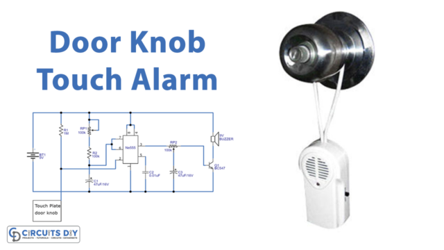
Have you had enough of stressing about whether or not your car is secure? Look no further than the anti-theft automobile alarm circuit! This innovative device not only deters potential thieves but also provides peace of mind for car owners. Imagine being alerted of any suspicious activity through loud sirens and flashing lights.
The Anti Theft Automobile Alarm Circuit provides security for your vehicle. It’s like having your own personal security guard for your car, 24/7. Say goodbye to the fear of car theft and hello to added convenience and protection with the Anti Theft Automobile Alarm Circuit.
Hardware Required
You will require the following hardware for Anti Theft Automobile Alarm Circuit.
| S.no | Component | Value | Qty |
|---|---|---|---|
| 1. | Polar Capacitor | 100uF | 1 |
| 2. | non-Polar Capacitor | 1000pF | 1 |
| 3. | Transistor | 2N3904, 2N2706 | 3,1 |
| 4. | Resistor | 100, 100k, 27k, 10k, 82 | 1, 1, 1, 1, 1 |
| 5. | Diode | 1N4001 | 1 |
| 6. | Coil | 100r. min | 1 |
| 7. | Battery | 12V | 1 |
| 8. | Switch | – | 6 |
| 9. | Speaker | 75R | 1 |
Steps to make
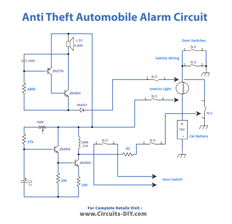
Follow the circuit diagram and connection table to make the auto alarm circuit.
Circuit Diagram
Connections
Here is a summary of the connections in the anti-theft automobile alarm circuit:
- The 12V battery is connected to the interior light, which has an integral switch (S1).
- The two-door switches (S2 and S3) are connected in parallel and activate quickly when a door is opened.
- Q1 and Q2 form the tone oscillator and operate a small speaker that is included in the case.
- When S2 or S3 are closed by a door being opened, 12V is applied to the oscillator through leads A (negative) and B (positive).
- Q3 and Q4 make up the horn sounder section, and when the 12V supply is applied to leads A and B, capacitor C2 begins to charge through R2 and RV1.
- When Q3 conducts, the base of Q4 becomes positive, causing Q4 to conduct and activate the relay.
- The circuit also includes a master switch (S4) that can deactivate the alarm and an adjustable delay through RV1.
- The external leads are organized using three separate cords: one twin for the horn switch circuit, one twin for the master switch S4, and one 3-core for circuits A, B, and C.
Working Explanation
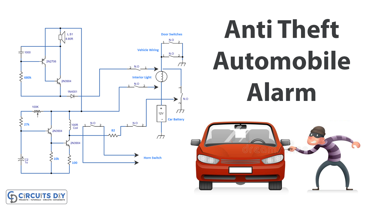
The circuit is divided into three sections: the car wiring, the tone oscillator, and the horn sounder.
Car Wiring:
- Thick lines in Fig. 1 represent this circuit section. It includes a 12V battery that powers the interior light and has an integral switch (S1). The two-door switches (S2 and S3) are in parallel and activate quickly when a door is opened. The car wiring does not need to be disturbed for the circuit to function.
Tone Oscillator:
- The tone oscillator section serves two purposes: it alerts the user that the circuit is in use and deters potential thieves with its warning sound. The tone oscillator is made up of Q1 and Q2 and operates with a small speaker included in the case. When S2 or S3 are closed by a door being opened, 12V is applied to the oscillator through leads A (negative) and B (positive).
Horn Sound:
- The horn sounder section is made up of transistors Q3 and Q4 and a relay. When the 12V supply is applied to leads A and B, capacitor C2 begins to charge through R2 and RV1. When Q3 conducts, the base of Q4 becomes positive, causing Q4 to conduct and activate the relay. The relay contacts RC1 close, and the relay remains locked even if the door is shut, opening S2 or S3. The second set of contacts, RC2, completes the circuit to the horn. If the door is shut before the relay locks on, the charging of C2 is interrupted, and the horn is not activated. This is essential to ensure that the owner can get out of the car without activating the alarm.
The circuit also includes a master switch (S4) that can deactivate the alarm and an adjustable delay through RV1. The external leads are organized using three separate cords: one twin for the horn switch circuit, one twin for the master switch S4, and one 3-core for circuits A, B, and C. The relay is bolted to the end of the case and uses two sets of “On” contacts that close when the relay is energized. It can pull on at a current of around 30-40mA roughly.
Final Words
This article details the steps necessary to build a car alarm circuit to deter theft at home. The anti-theft automobile alarm circuit protects your vehicle from theft by sounding an alarm when the doors are opened without the proper disarm procedure.
The circuit is not complicated and uses components that are reasonably priced. We hope you found this article informative and valuable and learned something new about this circuit. Please let us know if you have any questions or comments.