Automatic emergency products like tube lights and bulbs are becoming very popular as these become elegant solutions for situations where you can expect the AC power to go down sometimes from a few minutes to a few hours and you do not want the place/area to go into total darkness. Emergency lights are very crucial in some situations, the traditional emergency light uses a fluorescent tube as a light source. Therefore it provides light up to a maximum of 2 hours to 3 hours.
When we use white LEDs instead of fluorescent tubes it will give light for up to 7 hours approximately. So an automatic LED emergency Light circuit is designed to turn ON when there is no adequate lighting or if the power supply is cut-off. Earlier fluorescent lights were used to build such circuits. But the use of LEDs has proven to provide adequate lighting for a longer period before draining the battery. Here we construct a circuit with easily available components.
Hardware Required
| S.no | Component | Value | Qty |
|---|---|---|---|
| 1. | Step Down Transformer | 9-0-9V | 1 |
| 2. | Diode | 1N4007 | 6 |
| 3. | Positive Regulator IC | LM7808 | 1 |
| 4. | LDR | 5mm | 1 |
| 5. | Transistor | BC548 | 1 |
| 6. | MOSFET | IRF540 | 1 |
| 7. | Resistor | 1KΩ,10KΩ | 3,1 |
| 8. | Variable Resistor | 10KΩ | 1 |
| 9. | LED | – | 1 |
| 10. | White LED Array | – | 1 |
| 11. | Capacitor | 470uF,0.1uF | 1,1 |
| 12. | On/Off Switch | – | 1 |
| 13. | Connecting Wires | – | – |
| 14. | Battery | 6V, 4.5Ah | 1 |
Circuit Diagram
Working Explanation
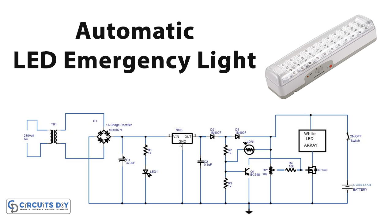
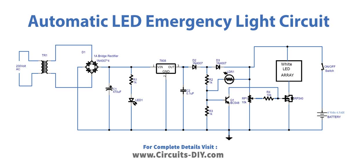
As we can see in the circuit, the first stage of the circuit has a step-down transformer (9-0-9V). Here the step-downed AC voltage is rectified by the 1 Amps bridge rectifier, you can also use the bridge rectifier module. Then the LED connected with resistor R1 gives the status about output DC voltage from the bridge rectifier. To regulate this DC output we have placed a positive regulator IC 7808, through which the DC voltage is regulated. Now this regulated supply is fed into the light-sensing circuit. Then the light sensing circuit by using normal 5mm LDR detects the light. This LDR provides low resistance when feels light and gives high resistance to the supply flow when feels dark conditions. Here VR1 10KΩ variable resistor is used to vary the sensing level of LDR. The only required adjustment is preset which has to be set to ensure the LEDs just light up (it should be left at that position). The 5mm LDR is just mounted on top of the emergency light as shown in the diagram. LDR is used to avoid it lighting up during daytime or when the room lights are ON. 2 LEDs are used in series; the dropping resistance is avoided and 2 LEDs light up with the current that is required for a single LED, by which energy is saved to a great extent.
When there is light LDR allows supply through it to the Q1 transistor base, hence the Q1 transistor turns ON and connects the MOSFET gate terminal to the ground so the LED array is disconnected from the DC bias ground supply. When dark condition arrives the LDR blocks current flow through it so the Q1 transistor base receives minimum voltage that is not turned ON the transistor. Therefore the Q1 transistor remains in OFF condition there is no current flow between the collector and emitter, so the emitter will be open. Now as no voltage is received at the gate terminal of MOSFET. Then the current flow occurs between the drain and source terminals so that the LED array glows. The battery (6 volts, 4.5Ah) is connected across the bias when a power failure occurs this battery provides the power supply to the circuit.
Applications
- The circuit is useful where there are load-shedding issues.
- Can be used in street lights.
- Also, can be employed to avoid sudden power failures at workplaces.