Introduction
Electricity is a part of our daily lives and hence the automation circuitry. Automation circuits are part of every home, industry, office, etc. The fuse panel or electrical board is installed in every house. But the protection of this circuitry is also the critical yet crucial part. An unexpected electricity occurrence like a blown fuse can destroy the whole circuitry and is also not promising for the environment. Thus, some elements cause a blown fuse. For example, if the wrong type of fuse gets installed, it may give considerable harm. In the same vein, the short circuit can also damage the whole panel. Moreover, sometimes damaged wiring can also affect the circuitry. Therefore, the blown fuse indicator should also get installed.
So, we are here to make an indicator so that if any blown fuse happens, it will show with the help of LEDs. Therefore, In this tutorial, we are going to make a “Blown Fuse Indicator”. We are making two simple circuits for this purpose. Firstly, we will make a simple blown fuse circuit and after that, we will create the dual-LED blown fuse circuit.
Hardware Required
| S.no | Component | Value | Qty |
|---|---|---|---|
| 1. | Transistor | BC547 | 2 |
| 2. | LED | 5mm | 1 |
| 3. | Bi-color LED Red, Green CC | – | 1 |
| 4. | Fuse | – | 1 |
| 5. | Resistor | 1K, 2.2K | 1, 2 |
Circuit Diagram

Working Explanation
Simple Blown Fuse Circuit
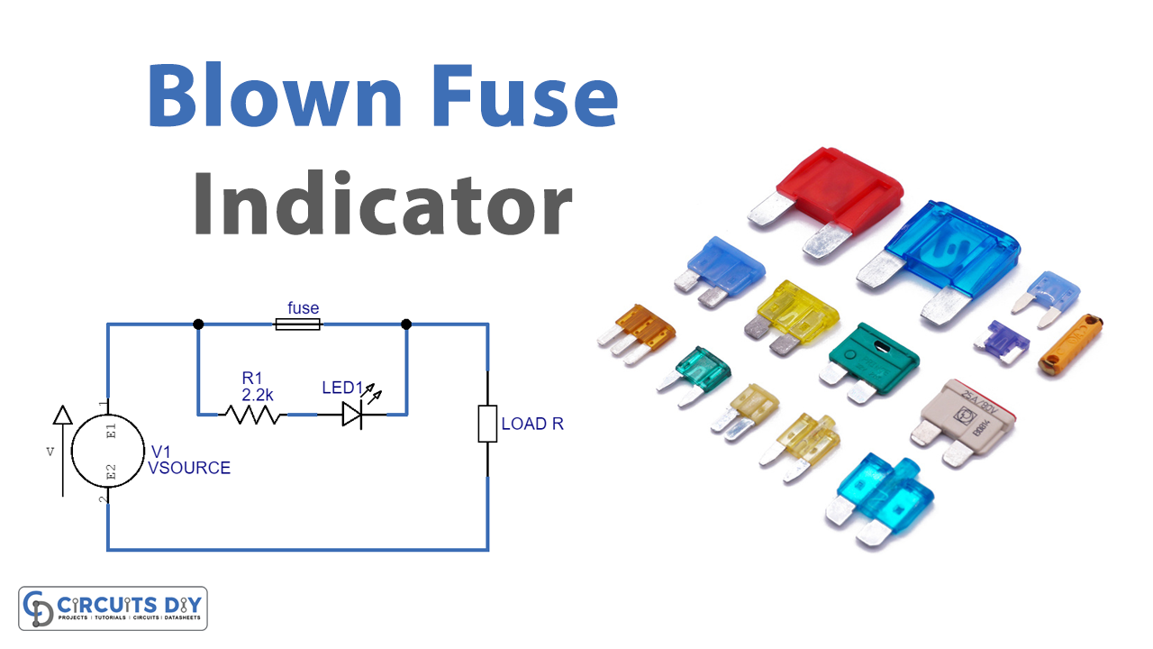
The simply blown fuse circuit indicator includes the resistor R1 that is connected with the LED in the series, while the fuse is connected in parallel. In normal conditions, the current flows through the fuse wire to the load due to the low resistance of the fuse wire. If any fault like a short circuit happens in the fuse the resistance of the fuse wire may get increased and the current flows through the R1 and hence LED starts to glow. This indicated the blown fuse.
Dual Blown Fuse Circuit
Dual blown fuse circuit includes two LEDs, the green LED that shows the good condition of the fuse, and the red LED that indicates the blown fuse. Resistor R1 is used to bias the collector of transistors Q1 and Q2. Both the transistor are working as a switch. In regular conditions, the current flows through R2 and triggers the base of transistor Q2 which drives the green LED, that is connected with the emitter pin of transistor Q2. At that time, since the resistance is higher at Q1, therefor red LED remains OFF. But, if a blown fuse happens, the current flows through R3, and transistor Q1 turns on which turns on the red LED. Hence, the green LED remains ON in natural conditions, while the red LED gets turned ON when the blown fuse happens.
Application and Uses
These circuits can be used In automation systems to indicate any type of electrical fault. For example,
- To show the damaged wirings.
- To indicate if any short circuit happens.
- Also, to show if there’s a ground fault.
- Moreover, it may also check if there’s a wrong fuse get installed.
- It may also help to indicate any damaged or faulty or outdated electrical outlets.
- To show if there’s any electrical burn.


