Introduction
Many times after making any gadget or circuit it would not work as expected. In this way, the principal thing an individual can do is to take an absolute look at the wire’s availability. Hence We can utilize Indicators for this reason. So, in this tutorial, we are going to make a “Broken Wire Detector”
Mostly we used multimeters for that reason to take a look at that if there is any broken wire. However, commonly, the circuits are extremely puzzling sometimes. In those conditions, It isn’t just difficult to check them physically but also this method takes a lot of time. Also, it is extremely difficult to take a look at modern hardware with this strategy. Subsequently, we want a certain circuit that can deal with this issue.
Hardware Required
| S.no | Component | Value | Qty |
|---|---|---|---|
| 1. | IC | CD4069 | 3 |
| 2. | Buzzer | 5v | 1 |
| 3. | LED | – | 2 |
| 4. | NPN Transistor | BC547 | 1 |
| 5. | Diode | 1N4007 | 1 |
| 6. | Potentiometer | 20KΩ | 1 |
| 7. | Capacitor | 100nF, 470pF | 1,1 |
| 8. | Resistor | 1MΩ, 10KΩ, 220KΩ, 470KΩ, 330Ω, 1.2KΩ | 1, 1, 1, 1, 1, 1 |
| 9. | Battery | 9V | 1 |
| 10. | 2-Pin Connector | – | 1 |
Circuit Diagram
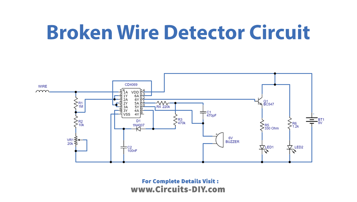
Working Explanation
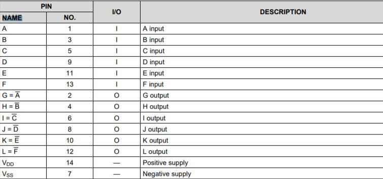
This Broken Wire Detector circuit uses the IC CD4069 which is a CMOS inverter IC, having 14 pins which include 6 six inverters inside. We give the pin configuration table of IC below.
The circuit uses the wire, but remember that the wire should not touch the AC supply directly. In this circuit Resistor R3, R4, and capacitor C2 assist IC CD4069 with the oscillation of signal and we apply it to the buzzer component, it becomes empowered while the recognition of EMF on the testing wire takes place, and two LEDs are associated with pin 12 of CD4069 with the help of transistor BC547. This circuit Q1 is a working switch and makes LED1 ON during EMF detection and makes LED2 ON during nonattendance of EMF. The potentiometer is in the circuit to adjust the sensitivity.
Application and Uses
- To detect the broken wires in various circuits.
- In troubleshooting devices, etc