Introduction
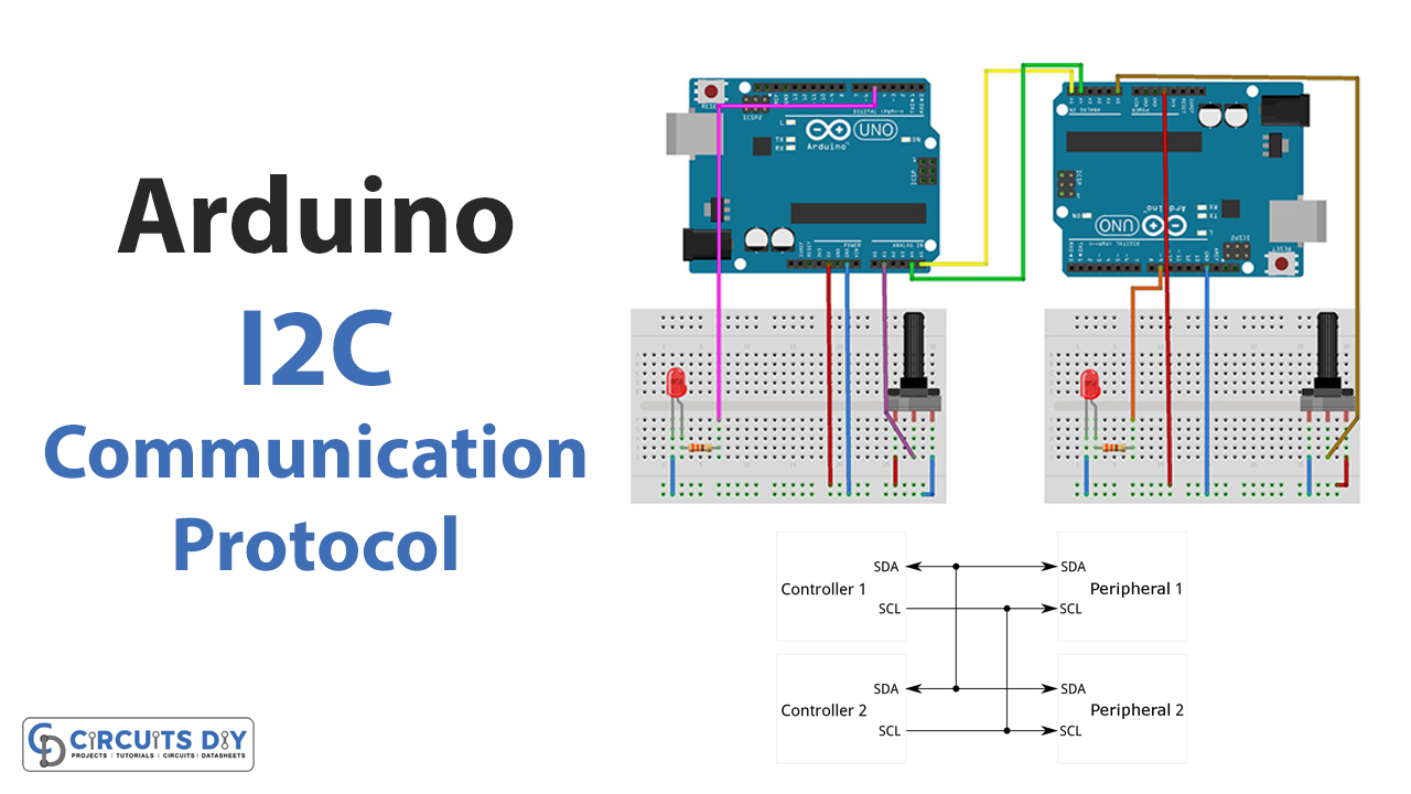
In this tutorial, we Connect Two Arduino Boards Using I2C Communication Protocol!
As a beginner, the question might arise in your mind: why connect two Arduinos? Because multiple Arduinos can increase your project’s possibilities; for example, one Arduino may control a display while another, motors or sensors. Each Arduino in a distributed system can have a specific job. One Arduino could be the master controller, sending instructions to other Arduinos that run different motors or sensors. By linking Arduinos, you can also construct a network of wireless sensors. So, there are many other ways to use two Arduinos together, depending on the project and its objectives.
What is I2C Communication Protocol?
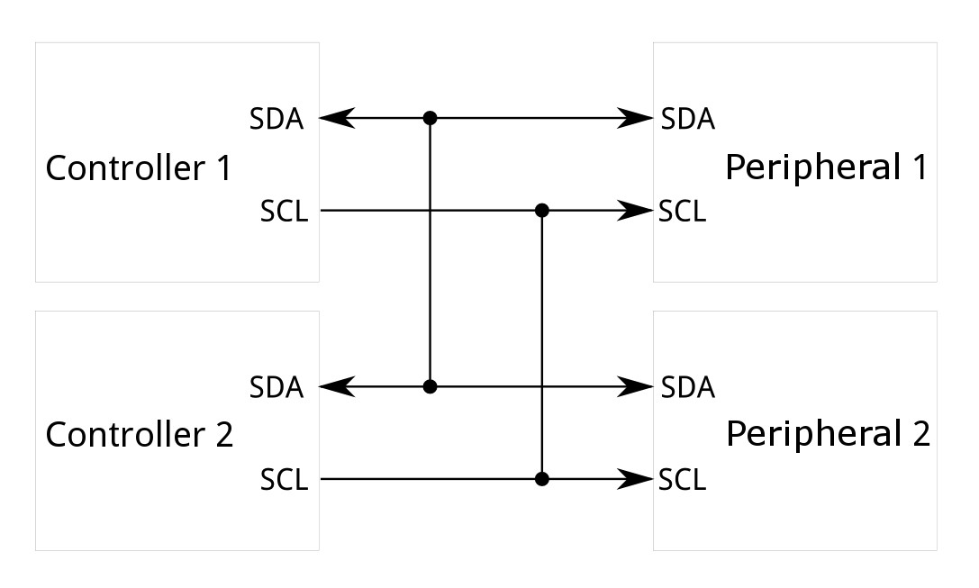
A common and frequently used serial communication protocol, I2C (Inter-Integrated Circuit), lets devices like microcontrollers communicate and share data with one another. It’s a primary, two-wire interface for linking electronic devices and exchanging data.
Hardware Components
You will require the following hardware to Connect Two Arduino Boards Using I2C Communication Protocol.
| S.no | Component | Value | Qty |
|---|---|---|---|
| 1. | Arduino UNO | – | 2 |
| 2. | Potentiometer | 5KΩ | 2 |
| 3. | LED | Red | 2 |
| 4. | Resistor | 330Ω | 2 |
| 5. | Breadboard | – | 2 |
| 6. | Jumper Wires | – | – |
Steps Connecting Two Arduino Boards Using I2C
To connect two Arduino boards, you need to follow the given steps:
Schematic
Make connections according to the circuit diagram given below.
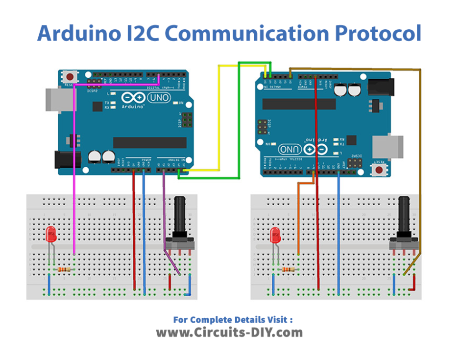
Wiring / Connections
| Arduino Master | Arduino Slave |
|---|---|
| 5V | 5V |
| GND | GND |
| A4 | A4 |
| A5 | A5 |
Installing Arduino IDE
First, you need to install Arduino IDE Software from its official website Arduino. Here is a simple step-by-step guide on “How to install Arduino IDE“.
Installing Libraries
Before you start uploading a code, download and unzip the following libraries at /Progam Files(x86)/Arduino/Libraries (default), in order to use the sensor with the Arduino board. Here is a simple step-by-step guide on “How to Add Libraries in Arduino IDE“.
Code
Now copy the following code and upload it to Arduino IDE Software.
#include <Wire.h>

int value = 0;

void setup() {
  Wire.begin(); // join i2c bus (address optional for master)
  Serial.begin(9600);

  pinMode(5, OUTPUT);
}

void loop() {
  int y = analogRead(A1);         //Read from A1 & Save to value
  value = map(y, 0, 1023, 0, 255);

  Wire.beginTransmission(8); // transmit to device #8
  Wire.write("Master value :  ");         // sends these bytes
  Wire.write(value);              // sends one byte
  Wire.endTransmission();    // stop transmitting

  Wire.requestFrom(8, 1);    // request 1 byte from slave device #8
  while (Wire.available()) { // slave may send less than requested
    int c = Wire.read(); // receive a byte as character

    analogWrite(5, c);
    Serial.print("Slave value : ");
    Serial.println(c);         // print the character
  }

  delay(100);
}
Let’s Test It
Now that you have completed the wiring and uploaded the code, it’s time to test the circuit! Adjust the potentiometers and observe how the values on the serial monitor and the brightness of the LEDs change.
Working Explanation
- First, we include the wire library for the 12C communication. Then, we make an integer variable value to store the value.
- We use the Wire.begin() function in the void setup to initialize the I2C communication. The Serial.begin() function initializes the serial communication. The pinMode() function sets the digital pin 5 as an output.
- In the void loop, we use the analogRead() function that reads the analog value from analog pin A1 and stores it in the y variable. The map() function scales the y value from 0 to 1023 to a range of 0 to 255 and stores it in the value variable.
- The Wire.beginTransmission() function begins transmission to the I2C device with the address 8. The Wire.write() function sends the string “Master value : ” and the value variable to the device. The Wire.endTransmission() function ends the transmission.
- The Wire.requestFrom() function requests 1 byte from the I2C device with the address 8.
- Wire.available() function checks if any bytes are available to read. If there are, the Wire.read() function reads a byte from the device and stores it in the c variable. The analogWrite() function writes the value of c to the digital pin 5. The value of c is also printed to the serial monitor using the Serial.println() function.
- In the end, the delay() function causes the program to pause for 100 milliseconds before repeating the void loop.
Applications
- To expand various electronic projects
Conclusion.
We hope you have found this Circuit very useful. If you feel any difficulty in making it feel free to ask anything in the comment section.