Introduction
UV radiation has so many uses in our daily lives. On the one hand, it may have some positive effects on one’s health; however, the excess amount can cause sunburn, skin issues, DNA damage, and skin cancer. As a result, UV radiation measurements are required. For this purpose, a device called a UV meter is employed. So, in this article, we will make a DIY UV Meter With Arduino and a Nokia 5110 Display.
It may appear to be a somewhat challenging DIY project, but if you read the instructions well and follow the steps in the correct order, it won’t be nearly as difficult for you as it may have seemed at first. So, let’s get started!
What is a UV Meter?
What we call a “UV energy meter” is a device that measures ultraviolet radiation. UV Index is the most common device available for this purpose. The UV Index was developed to assist individuals in better protecting themselves against ultraviolet radiation.
Hardware Components
You will require the following hardware for a UV Meter with Arduino.
| S.no | Components | Value | Qty |
|---|---|---|---|
| 1 | Arduino | UNO | 1 |
| 2 | UV Sensor | – | 1 |
| 3 | Nokia LCD | 5110 | 1 |
| 4 | Breadboard | – | 1 |
| 5 | Jumper Wires | – | 1 |
Steps for Making UV Meter
The hardware requirements for this DIY UV Meter are outlined above. To use them effectively, do as instructed once you get them:
Circuit Wiring / Connections
| Arduino | UV Sensor | Nokia 5110 LCD |
|---|---|---|
| 3.3V | +ve Pin | VCC |
| GND | -ve Pin | GND |
| A0 | S Pin | |
| A5 | ||
| D8 | CLK | |
| D9 | DIN | |
| D10 | DC | |
| D11 | CE | |
| D12 | RST |
Installing Arduino IDE
First, you need to install Arduino IDE Software from its official website Arduino. Here is a simple step-by-step guide on “How to install Arduino IDE.”
Installing Libraries
Before you start uploading a code, download and unzip the following libraries at /Progam Files(x86)/Arduino/Libraries (default) in order to use the sensor with the Arduino board. Here is a simple step-by-step guide on “How to Add Libraries in Arduino IDE.”
Code
The code of the project consists of 3 files.
- splash.c
- ui.c
- UVMeter.ino
Now copy the following code and upload it to Arduino IDE Software.
#include <LCD5110_Graph.h>

LCD5110 lcd(8,9,10,12,11);
extern unsigned char BigNumbers[];
extern uint8_t splash[];
extern uint8_t ui[];

String UV = "0";

void setup() {

 lcd.InitLCD();
 lcd.setFont(BigNumbers);
 lcd.clrScr();
 lcd.drawBitmap(0, 0, splash, 84, 48);
 lcd.update();
 delay(3000);

}

void loop() {

 int stringLength = 0;

 UV = readSensor();
 lcd.clrScr();
 lcd.drawBitmap(0, 0, ui, 84, 48);

 stringLength = UV.length();
 printUV(stringLength);
 lcd.update();
 delay(150);
}

void printUV(int length)
{
  switch(length)
  {
    case 1:  lcd.print(UV,38,19); break;
    case 2:  lcd.print(UV,24,19); break;
    default:  lcd.print(UV,0,19); break;
  }
}

String readSensor()
{
  String UVIndex = "0";
  int sensorValue = 0;

  sensorValue = analogRead(0);                        //connect UV sensor to Analog 0
  int voltage = (sensorValue * (5.0 / 1023.0)) *1000;  //Voltage in miliVolts

  if(voltage<50)
  {
    UVIndex = "0";
  }else if (voltage>50 && voltage<=227)
  {
    UVIndex = "0";
  }else if (voltage>227 && voltage<=318)
  {
    UVIndex = "1";
  }
  else if (voltage>318 && voltage<=408)
  {
    UVIndex = "2";
  }else if (voltage>408 && voltage<=503)
  {
    UVIndex = "3";
  }
  else if (voltage>503 && voltage<=606)
  {
    UVIndex = "4";
  }else if (voltage>606 && voltage<=696)
  {
    UVIndex = "5";
  }else if (voltage>696 && voltage<=795)
  {
    UVIndex = "6";
  }else if (voltage>795 && voltage<=881)
  {
    UVIndex = "7";
  }
  else if (voltage>881 && voltage<=976)
  {
    UVIndex = "8";
  }
  else if (voltage>976 && voltage<=1079)
  {
    UVIndex = "9";
  }
  else if (voltage>1079 && voltage<=1170)
  {
    UVIndex = "10";
  }else if (voltage>1170)
  {
    UVIndex = "11";
  }
  return UVIndex;
}
Let’s Test It
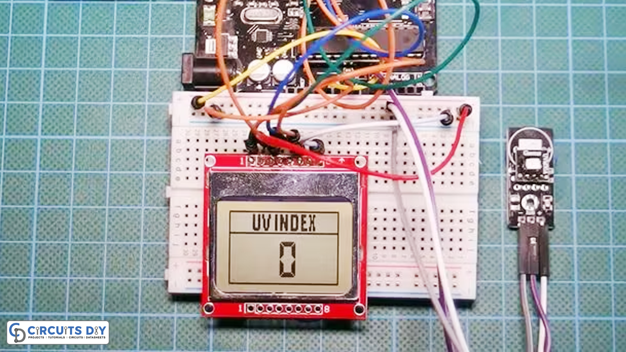
The next step is to test the circuit after it has been constructed. After uploading the code, the meter will show the calculated value when exposed to ultraviolet light.
Code Explanation
The project’s core code is not particularly complicated. Let’s dig into the code to understand how it works:
splash.c and ui.c.
First, understand that code includes two essential files, i.e., splash.c and ui.c.
- The splash screen’s binary values, which appear when the project boots up on the Nokia 5110 LCD, are contained in the first file, splash.c.
- The binary values for the user interface that appears after the project display the splash screen are contained in the file ui.c.
Main Code
- We declare some variables. We then initialize the display and show the splash screen. After that, we print the ui icon once before moving on to the next step: to read the analog value from the sensor once per second.
- There is a function, String readSensor(), that takes the analog value that was read from the sensor and turns it into a string that the UVIndex would use. It is just a simple if-else loop. After that, all left for us is to show that particular value on the display.
Working Explanation
Because this UV sensor is an analog sensor with linear output, it does not output the UV index directly. Its output voltage is based on how much UV light it detects. Therefore, the output voltage on its output pin will increase as the amount of UV light increases.
Applications
- Medical applications
- NDT inspections
- Clinical sterilizing lights, etc
Conclusion
We hope you have found this DIY UV Meter With Arduino and a Nokia 5110 Display Circuit very useful. If you feel any difficulty making it feel free to ask anything in the comment section.
Related posts:
 How to make Flame Sensor with Buzzer using Arduino
 BME280 Temperature, Humidity, and Pressure Sensor Module with Arduino
 How to Interface BME680 Environmental Sensor with Arduino UNO
 Interfacing FPM10A Fingerprint Sensor with Arduino UNO
 Toggle LED with Button - Arduino Tutorial
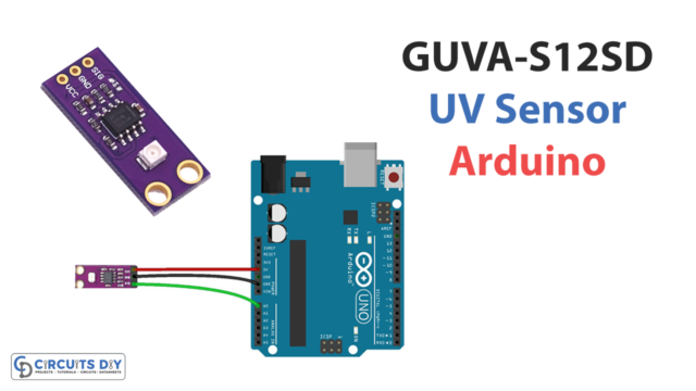 Interfacing GUVA-S12SD UV Sensor Module with Arduino