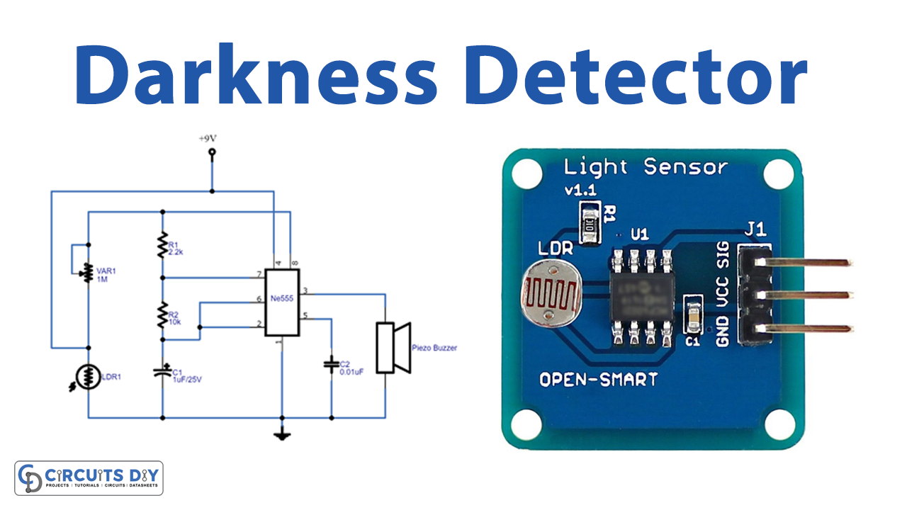
In this tutorial, we are going to make a “Darkness Detector Circuit”.
A circuit that detects darkness or the absence of light is known as a darkness detector or dark detector. As we know that we always try to do and make things that save energy/power, a dark detector circuit can also help us in the same cause by automatically controlling and turning ON-OFF lights or any loads depending on the brightness of ambient light. For example, street lights; manually turning on those lights necessitates someone performing that task every day. On the other side, if we automate this process by employing a dark sensor that detects darkness and switches on automatically, we would save energy, power, and time. Here we design a simple circuit with LDR (Light Dependent Resistor) and timer IC 555, It will produce a buzzer beep sound when the shadow or darkness occurs on the LDR. We can employ this circuit where we need to know the change in light intensity or darkness, it can be used as an alarm circuit or as a watchdog circuit and it can be used in so many ways.
Hardware Required
| S.no | Component | Value | Qty |
|---|---|---|---|
| 1. | LDR (Any size) | – | 1 |
| 2. | IC | NE555 Timer | 1 |
| 3. | Piezo Buzzer | – | 1 |
| 4. | Variable Resistor | 1MΩ | 1 |
| 5. | Resistor | 2.2KΩ, 10K | 1, 1 |
| 6. | Capacitor | 1uF/25V, 0.01uF | 1, 1 |
| 7. | Connecting Wires | – | – |
| 8. | Battery | 9V | 1 |
Circuit Diagram

LDR (Light Dependent Resistor)
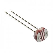
LDR (Light Dependent Resistor or Photo-Resistor). The resistance of LDR depends on the intensity or brightness of light incident on it and the relationship is of inverse proportionality. This means that when the intensity of light increases, the LDR’s resistance reduces means if there is no light then it becomes an MΩ resistor, if light falls on it then it may become a few Ω resistor. It comes in different sizes from 5mm to 20mm depending on the LDR size sensitivity may change slightly. This LDR element will have two terminals and one semitransparent CdS (Cadmium Sulfide) layer and the impurity semiconductor makes this device photosensitive depending on the light intensity. As we know the resistance of this device will vary depending on light, this character is used in many light-related applications.
Working Explanation
The circuit is very similar to the ASTABLE MULTIVIBRATOR, with only one modification. Which is done at RESET pin (PIN4). In a normal ASTABLE vibrator, this pin is connected to +V, but since in this case we are supposed to generate a pulse on the condition of the absence of light it is not connected directly to +V. The timing resistors R1, R2, and timing capacitor C1 are connected between Vcc and GND. The discharge pin is connected between R1 & R2 then the threshold, trigger pins are commonly connected between R2 and C1.
The LDR is connected with variable resistor VaR1 and the RESET pin is connected between VaR1 and LDR. The resistor network provided at the RESET pin provides a virtual ground to keep resetting the IC, hence the square wave output is stopped in the presence of light. Now power supply is applied to the LDR through VaR1, we can change the sensitivity level of LDR through variable resistor VaR1. Now when the darkness falls on the LDR, the resistance of the LDR increases drastically, this increase of resistance in the second branch (one with LDR) of the voltage divider will be enough to change the ratio of voltage sharing between the two branches of the voltage divider section. Once this happens, the potential at the junction of the voltage divider circuit rises. And similarly, the voltage at the RESET pin rises. This rise in voltage will be enough to lift the 555 IC from reset mode. Once this reset mode is lifted, the timer generates a square wave output.
So, when the LDR detects the darkness then timer IC 555 gets a Reset signal and starts to produce a square pulse at the output pin, this may drive the buzzer and produce a beep sound. You need to calibrate the circuit to detect exact darkness. It produces a buzzer sound for a few seconds, you can change output time by changing the C1 Value. The buzzer here can be replaced with LEDs to create an output response of lighting. So once the LEDs are placed and the darkness falls, we will have an emergency backup light.
Applications
- It can be used where automatic switching of light is required.
- Used as a security measure in homes, buildings, or workplaces.