Introduction
Using a simple lock key for security in the present day, when everything is based on technology, is absurdly outdated. Even today’s invaders make use of technology. As a result, we must utilize some type of lock circuit to safeguard our houses, businesses, banks, lockers, and other areas that require security. Not only is it safe, but it also allows the user to get updates or news via an alarm when someone passes by. So, in this tutorial, we are going to make a “Door Open Alarm Circuit using Reed switch”.
A door alarm circuit is a signaling or security alert device that activates when the device-connected door is opened. And the alarm will continue to be activated as long as the door is left open.
Reed switches have a high level of dependability for a mechanical switch. They may also function in explosive conditions where a spark might have fatal consequences due to their sealed architecture. Although reed switches are an older technology, they are far from being outdated.
Hardware Components
The following components are required to make Door Open Alarm Circuit
| S.no | Component | Value | Qty |
|---|---|---|---|
| 1. | Transistor | BC547, SL100 | 1 |
| 2. | Diode | 1N4007 | 1 |
| 3. | Buzzer | – | 1 |
| 4. | LED | – | 1 |
| 5. | 2-Pin Connector | – | 1 |
| 6. | Reed Switch | – | 1 |
| 7. | Potentiometer | 50K | 1 |
| 8. | Resistor | 300Ω, 1KΩ, 2.2KΩ | 1,1,1 |
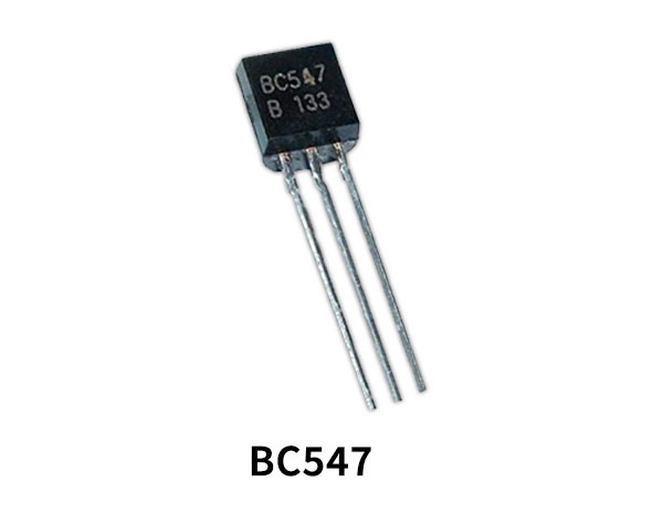
BC547 Pinout

For a detailed description of pinout, dimension features, and specifications download the datasheet of BC547
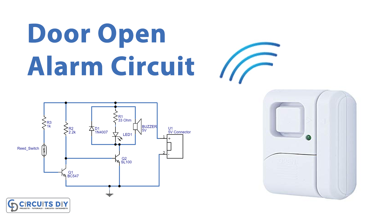
Door Open Alarm Circuit
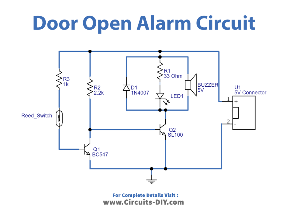
Working Explanation
In this Door Open Alarm Circuit using a Reed switch, when there is someone around the reed switch device, the magnetic force gets generated parallel to the sensor. This magnetic force builds the whole magnetic circuit and gives opposite polarities to the contacts of a reed switch. Hence they attract each other, and the current starts to flow in the circuit.
We made this alarm circuit up of two common transistors, the BC547 and the SL100. Here, the SL100 NPN transistor functions as a switching device to turn on, or off the buzzer, with a 5V DC supply fed directly into the Reed switch through resistor R3 and another reed switch terminal connected to the Q2 transistor base. We directly linked the base terminal of the Q1 transistor to the collector of the Q2 transistor. Not only is it safe, but it also allows the user to get updates or news via an alarm when someone passes by. As a result, the buzzer beeps, and LED glows.
Application and Uses
- In the home, office, and industrial automation.
- In banks, private lockers, etc.
- Can also be utilized in automotive applications.