Introduction to Doorbell Circuit
Ding dong!! There goes the doorbell. So, Like this previous verse, we have heard and read so much poetry related to doorbells. In other words, that’s the most common thing. Also, it exists at every entrance door of the houses. For the students of electronics, everything that has electronics excites them more. Therefore, you must have thought about the circuitry inside the Doorbell Circuit or device. So, in this article, you are going to learn how to make the Doorbell Circuit. The circuit is simpler to make for those having little understanding of electronic circuits.
The circuit contains a NE555 timer IC. To keep the circuit and IC away from damage, try to mount ICs on IC holders. Use a promising quality Printed circuit board to make a circuit. The circuit has a switch that is push-button.
Hardware Required
| S.no | Component | Value | Qty |
|---|---|---|---|
| 1. | PCB/ Veroboard | – | 1 |
| 2. | IC | NE555 | 2 |
| 3. | Potentiometer | 100K | 2 |
| 4. | Resistors | 1K, 4.7K, 10K | 1, 1, 1 |
| 5. | Capacitors | 0.01uf, 33uf/25V, 100uf/25V | 3, 1, 1 |
| 6. | Push-button Switch | – | 1 |
| 7. | Speaker | – | 1 |
| 8. | DC power | 9V | 1 |
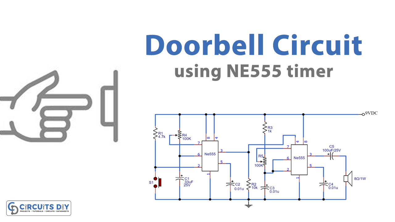
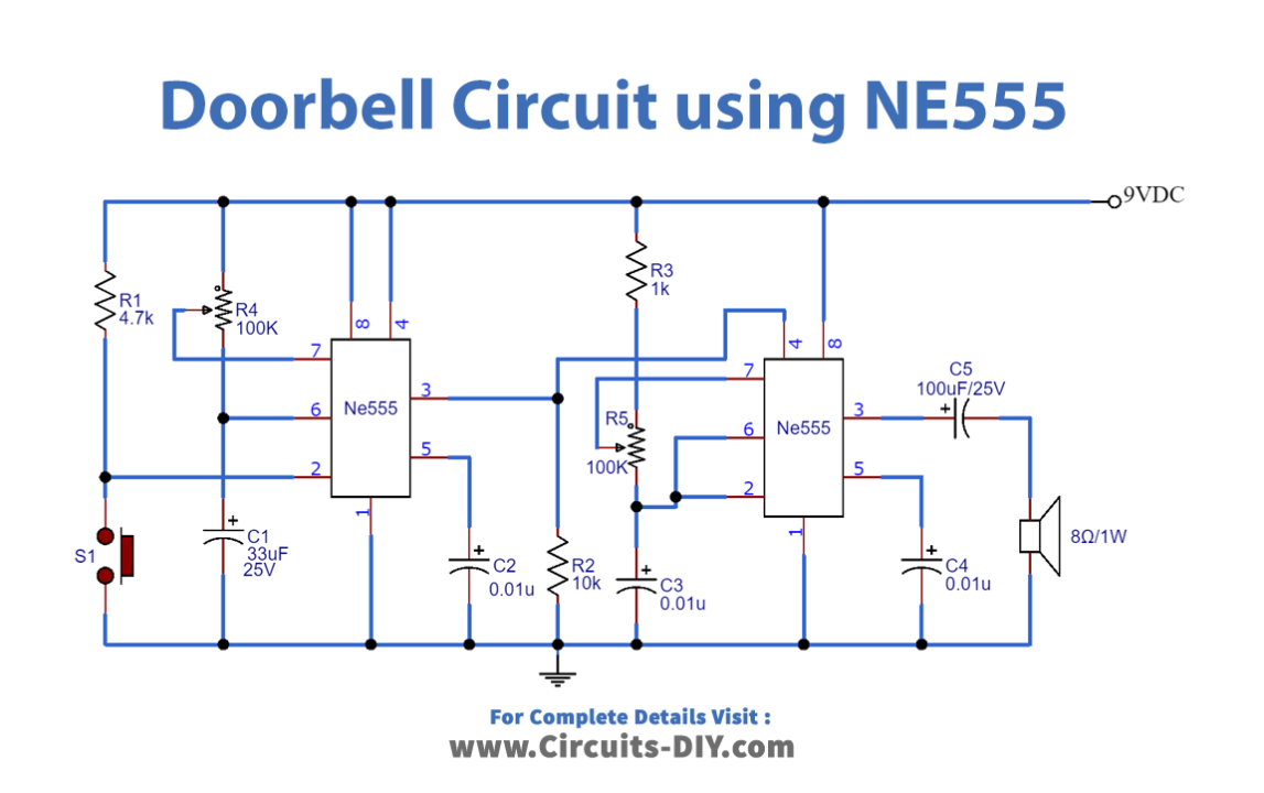
Circuit Diagram of Doorbell Circuit
Working Explanation
When the switch of the doorbell Circuit is pressed, the IC gets active. Because the output of the switch is connected to the input pin 2 of the IC. So, put triggers the IC. After that, the output of the IC at pin 3 gets high for the period that is set by the potentiometer R4. Further, this output refers to the IC2, and it starts oscillating to make a sound through the speaker connected. Moreover, this IC2 is connected as a stable multivibrator. Hence, the frequency of the multivibrator increases or decreases the potentiometer R5. Modification in the sound is possible by changing the resistance of potentiometers connected to the circuit.
Application and Uses
- Firstly, it is pretty much found in every house
- Further, with some modification, vehicles can also use this circuit