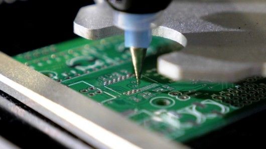
Introduction
There are so many issues that occur during and after the manufacturing of printed circuit boards. But, some signal integrity issues can also damage the PCBs. One of the factors that degrade signals is the Electromagnetic issues in PCB. It increases with the increase of frequency and with an increase of faster rise time. It disrupts the signals in electromagnetic devices.
An Overview of Electromagnetic Issues
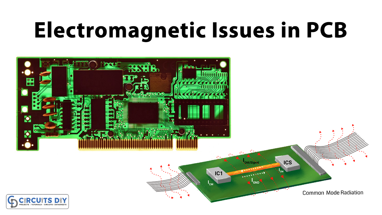
Electromagnetic issues in PCB are also familiar with radio-frequency interference. It is the disturbance by external sources that can induce an electrical circuit and can damage the printed circuit board. This interference can also degrade the performance of the printed circuit boards. This unwanted energy happens because of the emission and radiation. EMI also occurs if the PCB is using integrated circuits. Because integrated circuits are one of the sources that generate Electromagnetic issues. But, many of the other components also generate some EMI in the circuit And, that’s why designers use heat sinks in the printed circuit boards to radiate significantly.
Classification of Electromagnetic Issues
EMI can be classified into some types that are based in terms of some factors. Those factors and their further classifications are described below:
* In terms of the Sources
There are only basic sources that induce an EMI in PCBs:
- Man-made EMI: This occurs because of the other devices in the vicinity of that particular device. This includes radio frequency interference and noise.
- Natural EMI: This type of EMI occurs because of an electric shock, lightning, or any other related occurrence
* In terms of the bandwidth
EMI can also be classified using their bandwidths:
- Narrowband EMI: Narrowband EMI usually consists of one frequency or a narrow band of frequencies. It generates a very minor EMI impact on the device. Hence, not very dangerous if it is kept within acceptable limits.
- Broadband EMI: Broadband EMI consists of a large magnetic spectrum. And can cause greater EMI problems in the circuit.
* In terms of Duration
Based on the duration there are two types of an EMI. that is, continuous EMI and an impulse EMI:
- Continuous EMI: An EMI that is continuously emitted from any of the sources. The source can be natural as well as man-made.
- Impulse EMI: An EMI that occurs for a short duration is an impulse EMI. It can also be from man-made or natural sources. An example of impulse EMI is the noise from lighting, switch, etc
How to Reduce Electromagnetic Issues in PCB
Every problem has a solution in this world. In the same way, some principles can help to reduce or fix the EMI issues:
- SMD Technology: Surface mount devices offer closer placement of the components. And, It also allows lower inductance. This helps in the reduction of EMI
- 45 Degree Angle: Instead of the right angle, use a 45-degree angle. This will not increase the capacitance present in the circuit.
- Trace Spacing: Separate traces of different signals. Utilize the shunt and ground traces for clock lines. And, route differential traces closely.
- Ground planes: To reduce EMI, use full ground planes. Hence, avoid the long paths. Remember, to avoid the copper fill areas
- Cable Shielding: Cables carry digital and analog signals that may have parasitic capacitances. This can increase the EMI issues on the PCB. Therefore, use the cable shielding to avoid this.
- Decoupling Capacitors: To reduce the power rail noise in the circuit, use the decoupling capacitors. Also, connect ground capacitors to the ground planes
- Control the Impedance: The impedance of the transmission line depend on numerous factors. That is the speed, RF energy, and also material of PCB. By controlling these factors the impedance can get controlled