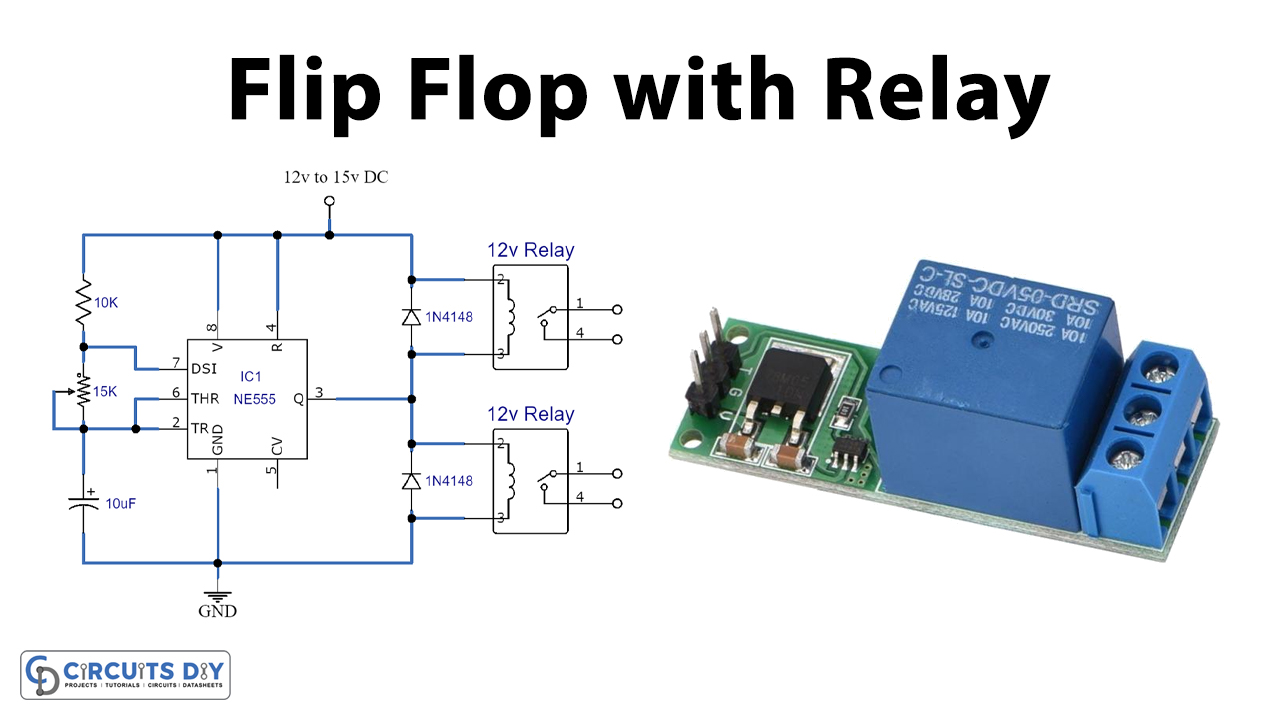
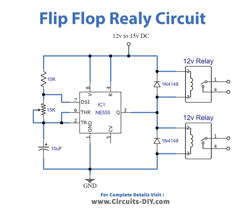
Flip flop relay is an electrical circuit that acts as a bistable multivibrator it means it has two stable states that are on and off and the states are constantly shifting. The relay-connected switch will continue to turn on and off one after another continuously in a flip-flop manner producing the blinking effect of light. You may attach both DC and AC devices with the relays to get flickering and flashing impact.

Hardware Components
The following components are required to make Flip Flop Relay Circuit
| S.no | Components | Value | Qty |
|---|---|---|---|
| 1. | Resistor | 10K | 1 |
| 2. | Relay | 12v | 2 |
| 3. | IC | NE555 Timer | 1 |
| 4. | Diodes | 1N4007 | 2 |
| 5. | DC power supply | – | 1 |
NE555 IC Pinout

For a detailed description of pinout, dimension features, and specifications download the datasheet of 555 Timer
Flip Flop Relay Circuit
Working Explanation
The circuit is quite easy to build and only requires a few external components. Flip flop relay circuit can be run from a DC supply of 12 to 15 volts. A 100K potentiometer is used to change the relay flip flop intensity per second. The back EMF in the circuit is restricted by using two diodes 1N4007. IC NE555 can be used as an oscillator and also as a flip flop element to provide time delay. Two relays are used in the circuit. Relays are switches that electromechanically or electronically open and close the circuit. Relays track one electric circuit by touch opening and closing in another.
Applications and Uses
This circuit can be used in a number of devices such as light bulbs, LEDs, etc to produce a blinking or flashing effect