Introduction:
Adder is generally considered to be a digital circuit that is used to perform an addition operation. It takes the two bits as input and gives the output after performing addition. The adders are used in arithmetic and logic units in computer processors and other types of processors, they are used for increment or decrement operations or calculate addresses or indices, etc. There are two types of adders in digital electronics half adder and full adder.
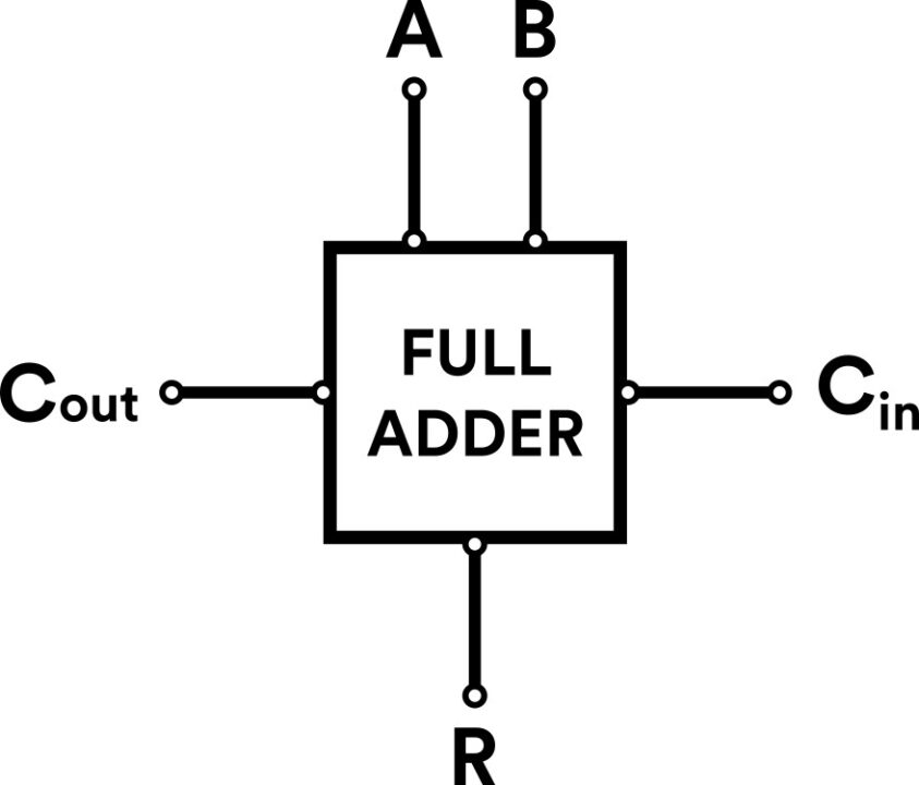
A half adder adds two bits and gives an output in two bits while a full adder circuit has three inputs, two inputs A and B, and the third from another adder which is then carried input and delivers an output in two bits. Here we will discuss a brief explanation of the working principle and the applications of a full adder circuit.
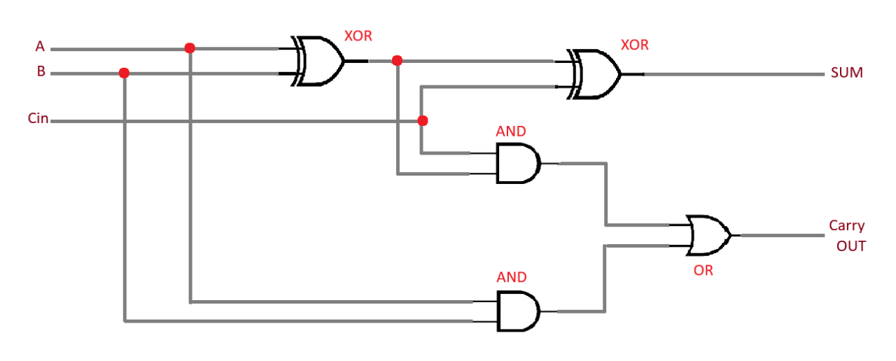
Full Adder Logic Gate Diagram:
It consists of two XOR gates, two AND gates, and an OR gate, the logic gate circuit diagram is given below:
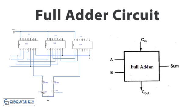
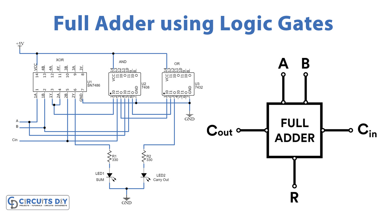
Full Adder Circuit Diagram:
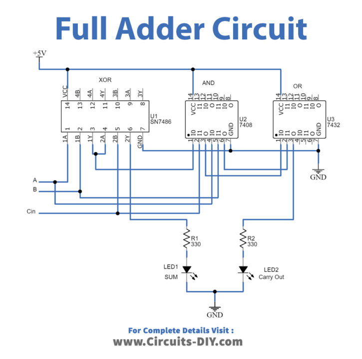
Full adder circuit diagram
Construction & Working:
A full adder circuit uses 7486 (XOR) IC, 7408 (AND) IC, and 7432 (OR) IC, all the three ICs are the two-input logic gates. The 5V DC supply is applied to the circuit. The A and B inputs are given to the XOR IC at pin 1 and 2, while the output of the XOR gate from pin 3 is given to the AND gate as input and input A as another input, the third input Cin is given to the pin 5 of the XOR IC while the pin 6 of XOR IC is taken as a result of addition which is connected to the LED1 through a resistor R1. The OR gate adds the output from the two AND gates and the output from the OR gate is taken at pin 3 as carryout is connected to LED2 through R2. The LEDs indicate the HIGH and LOW logic.
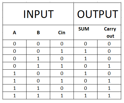
The full adder circuit takes A, B & Cin as input and gives Sum and Carry as outputs. Here the Sum is the exclusive addition of A, B, and Cin and Carryout is the OR logic between A.B and A⊕B and Cin.
- Sum = A⊕B⊕Cin
- Carry out = A.B + (A⊕B).Cin
Uses of Full Adder Circuit:
The full adder circuit has the following applications:
- ALU utilizes full adder circuits.
- ALU uses adders to generate memory addresses and make the counter of a program to point to the next instruction.
- Graphic processing units useful adders for graphics applications.
- This circuit can be used in larger circuits like Ripple Carry adder.