Introduction:
An electronic oscillator is an electronic circuit that generates repeated, continuous, oscillating waveforms. The oscillator has many types. The Hartley oscillator is one of the types of oscillator circuits in which the tuned circuit determines the frequency of oscillations. The tuned circuit consists of an inductor and capacitor which is also called LC tuned circuit.
Hartley oscillator was developed by an American engineer Ralph Hartley in 1915 and hence is named after him. The Hartley oscillator is designed with two inductors in series (a single tapped inductor) and the capacitor in parallel combination with the inductive coils to form a resonant tank circuit that generates the continuous sinusoidal oscillation. The feedback is obtained from the center connection of the two inductors needed to generate the oscillations. The working principle of the circuit is explained in detail below.
Hardware Components
The following components are required to make Hartley Oscillator Circuit
| S.no | Component | Value | Qty |
|---|---|---|---|
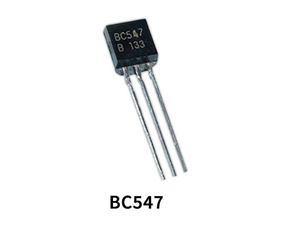
| 1. | Transistor | BC547 | 1 |
| 2. | Inductor | 10mH, 20mH | 1 |
| 3. | Capacitor | 100pF, 10pF, 100nF | 2, 1, 1 |
| 4. | Resistor | 100KΩ, 5KΩ, 1KΩ, 10KΩ | 1 |
| 5. | Battery | 9V | 1 |
BC547 Pinout

For a detailed description of pinout, dimension features, and specifications download the datasheet of BC547
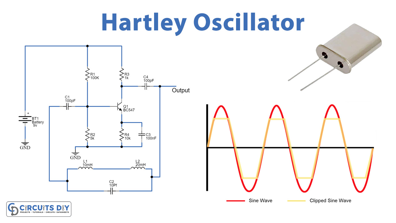
Hartley Oscillator Circuit

Working Explanation
The Hartley oscillator is a simple circuit that contains transistor BC547, a few resistors, inductors, and capacitors. The LC tank circuit in the Hartley oscillator is built using two inductors connected in series which is called tapped inductor and the capacitor in parallel with the series inductors. The transistor here is used as a common emitter amplifier to amplify the oscillating signal.
When the power supply is applied to the circuit, the current at the collector terminal starts to increase and the capacitor gets charged and then discharges through the two inductors in series hence the initial oscillations are generated. This oscillating signal across L1 is applied to the transistor at its emitter and base terminal for amplifying the signal which is then applied to the feedback tank circuit. This tank circuit produces a phase shift of 180° and the amplifier circuit also provides a phase shift of 180° therefore a total of 360° phase shifts is obtained at the output.
The formula for Hartley Circuit:
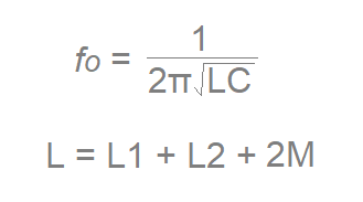
Note: 2M can only be used when two coils L1 and L2 are wound on the same core.
The circuit built is used for the range of frequency from 20KHz to 90KHz to generate sine wave signals.
Applications:
The Hartley oscilloscope is used in many applications which are discussed below:
- It is used to produce sinusoidal wave signals at the required frequency.
- It is also used in radio receivers.
- It is an appropriate radio-frequency oscillator of range up to 30MHz.
- Due to the broad range of frequencies, it is the most popular used oscillator.