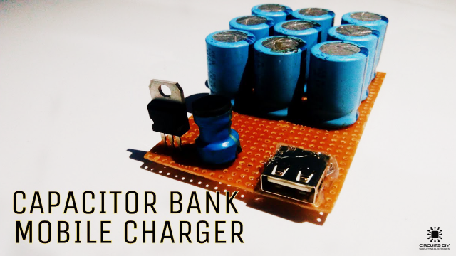
Introduction
Imagine you are on a picnic trip with your best friends and you pick out your phone to take a selfie and boom! It’s dead, or imagine you have a graduation ceremony where you want to capture the moments of joy with your mates and family and then you realized your phone’s battery is getting low, or imagine you are traveling and your boss calls you to submit a task immediately when there is no electricity. This all can create a little chaos for sure. And, no doubt charging your phone, laptop, or any other electronic equipment gets difficult when you’re traveling. And, for this, every one of us uses Power banks which store the electrical energy so that our devices can get charged later. So, in this tutorial, we will see How to make a Power Bank at Home.
A Brief History of Power Banks
The power bank was made in 2001 by a Chinese company called Pisen. The first design was two AA batteries. That first primary power bank was a little heavy and had short battery life. Today, there are substantially more complex and reduced designs with far better battery life. Present-day power banks can fit in the palm of your hand and easily charge your gadgets.
JLCPCB is the foremost PCB prototype & manufacturing company in china, providing us with the best service we have ever experienced regarding (Quality, Price Service & Time).
Hardware Components
The following components are required to make Power Bank Circuit
| S.no | Component | Value | Qty |
|---|---|---|---|
| 1. | USB female port | – | 1 |
| 2. | input pin | 12DC | 1 |
| 3. | Resistors | 1K, 33ohms | 1, 1 |
| 4. | Diodes | 1N4007 | 2 |
| 5. | LED | 2 | |
| 6. | IC | 7805 | 1 |
| 7. | Capacitor | 470uf | 1 |
7805 Pinout
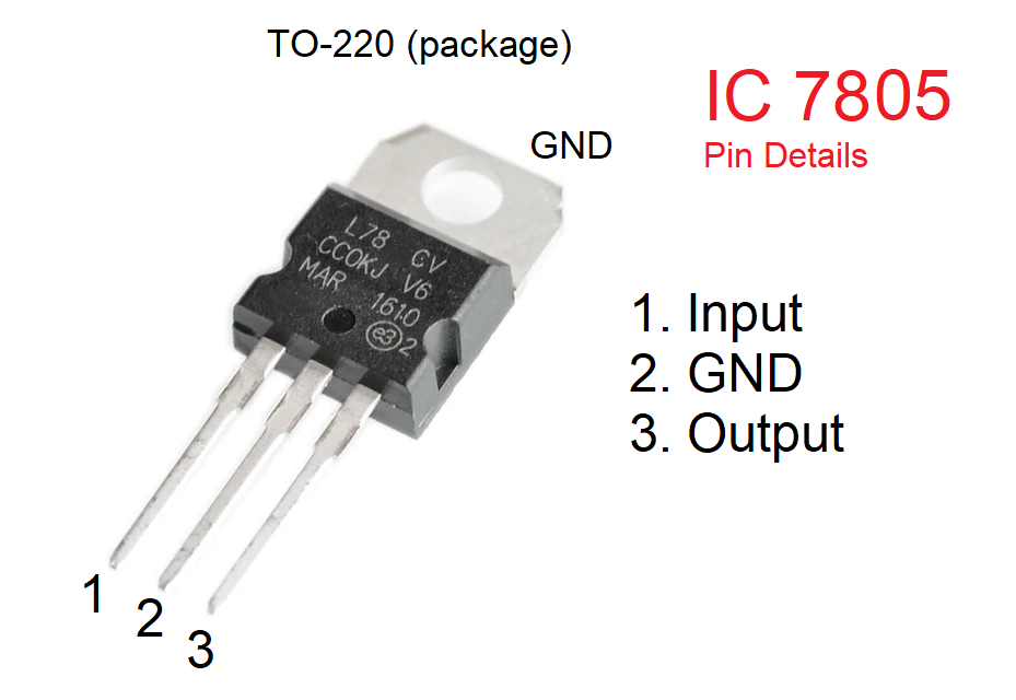
For a detailed description of pinout, dimension features, and specifications download the datasheet 7805
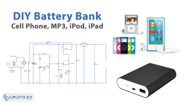
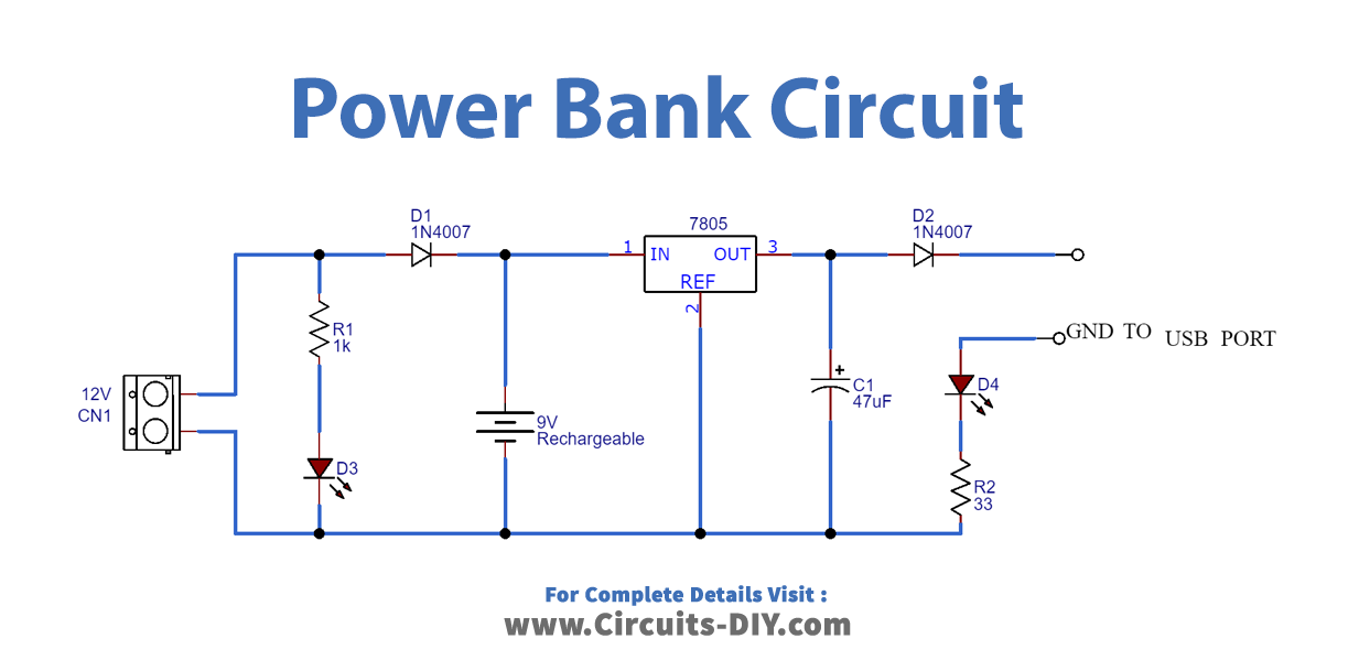
Power Bank Circuit
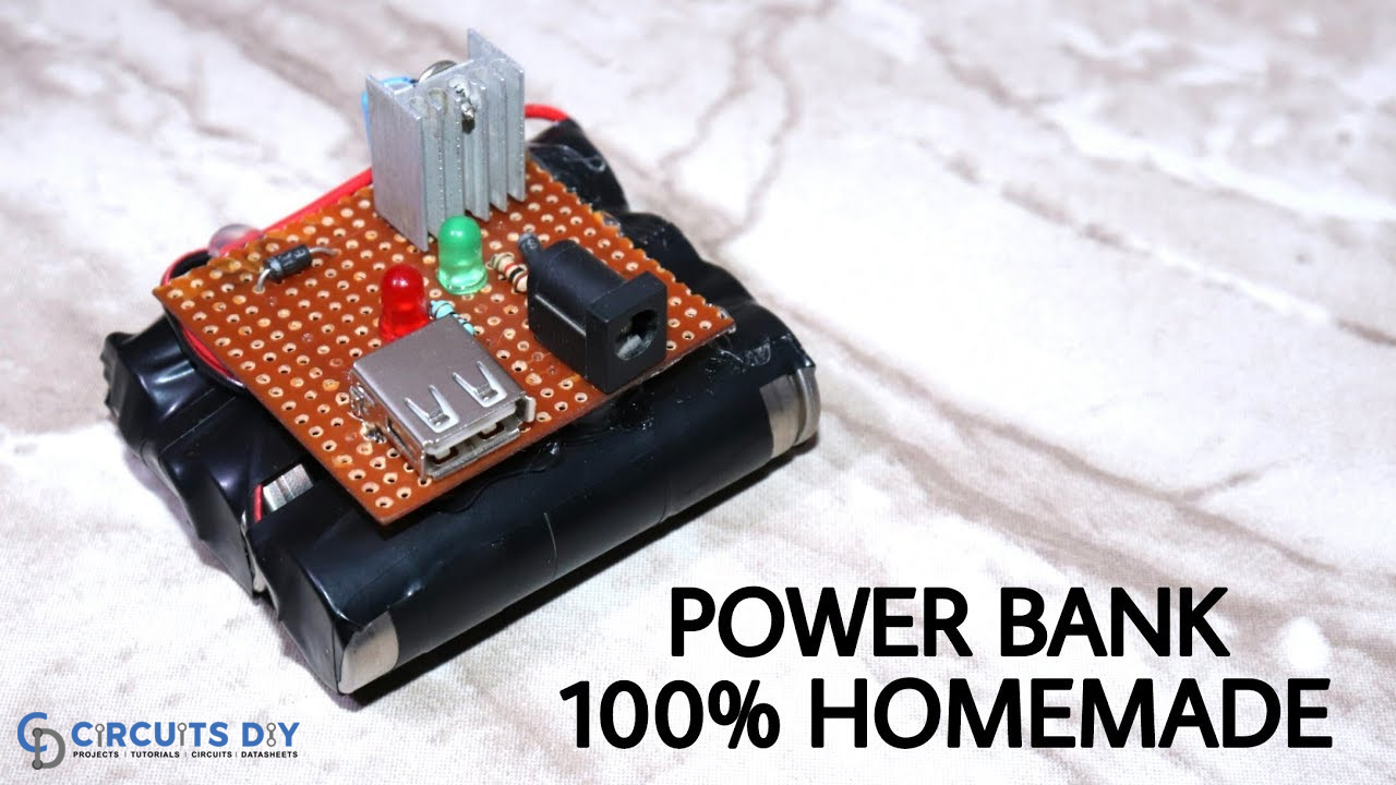
Useful Steps
- First place and solder the female USB port and 12DC input pin on the Vero board.
- Now, connect a resistance of 1K in a way that one end is connected to a 12V pin and one end to the positive pin of the LED. Connect the negative of an LED to a 12V negative pin.
- Then connect the diode’s positive (anode) to the 12V positive pin and negative (cathode) to pin 1 of 7806 IC. Connect the capacitor to the IC in a way that its negative is connected to pin 2 and its positive to pin number 3.
- Now take the second diode, connect its anode to pin 3 of an IC, and cathode to the Vcc pin of the USB.
- We then connect the second LED in a way that its negative goes to the 33 ohms resistance, and positive to the ground of the USB port. Also, the other end of 33 ohms resistance will be connected on 12 pins negative.
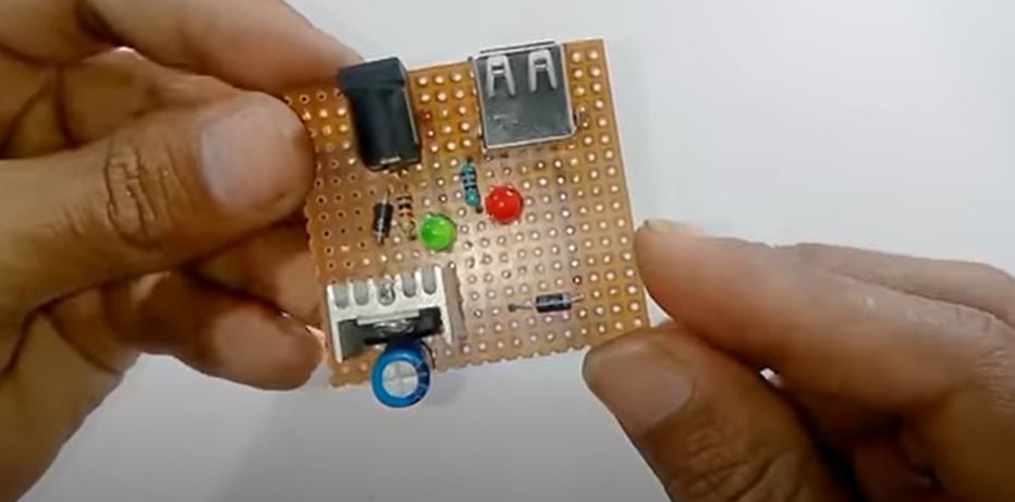
- The circuit would look like this:
Applications and Uses
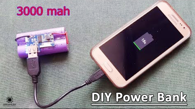
- We can use this circuit to charge electrical gadgets like cell phones, etc
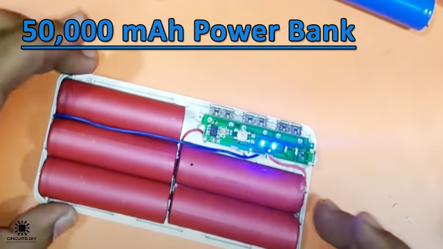
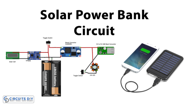
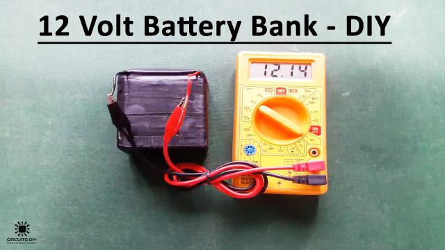
- We can modify it for different applications. For example, with some modifications, you can make solar power banks, high-capacity power banks, etc.