In this tutorial, we are going to make a “Solar Power Bank Circuit”.
The power bank is a battery pack that is used to charge electronic devices outdoors during emergencies when an AC outlet is unavailable for charging. As we know that the major drawbacks of communication lines come because of the distortion of electrical lines or lack of generation of electricity like in remote areas or during a disaster or natural calamities. To set back such drawbacks, we need a renewable source of energy that can function round the clock without any disruption. The solar power bank is one of a kind. It works on the power of the sun, converting solar to electrical, and helps in charging cell phones which can be used in communication, and thus, turns out to be vital during disasters and power outages.
The following solar power bank circuit design avoids hassles and we can charge our mobile or electronic gadgets whenever we want. This solar power bank circuit provides DC power through a USB connector and has a 1 Watt white LED for lighting needs. This power bank circuit can be built with an easily available breakout board. During disasters and power outages, it can be used with ease and with a long and forever durability of the device and power. Even in remote areas having a scarcity of electricity, such circuits can be used.
Hardware Required
| S.no | Component | Value | Qty |
|---|---|---|---|
| 1. | Solar Panel | 5V | 1 |
| 2. | Lithium Ion Battery-18650 | TP4056 | 2 |
| 3. | DC-DC Boost Converter | XL6009 | 1 |
| 4. | Toggle Switch | – | 2 |
| 5. | LED | – | 1 |
| 6. | USB Boost Converter | 3V to 5V | 1 |
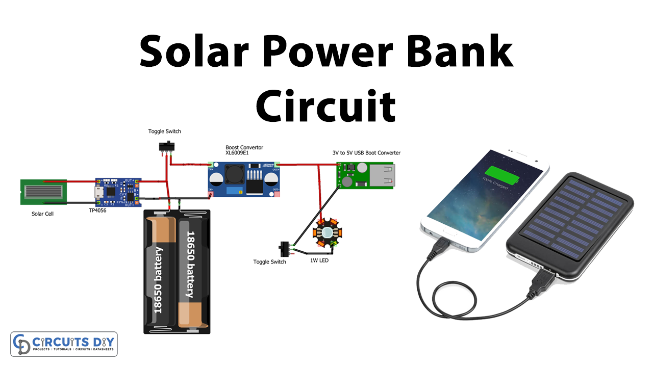
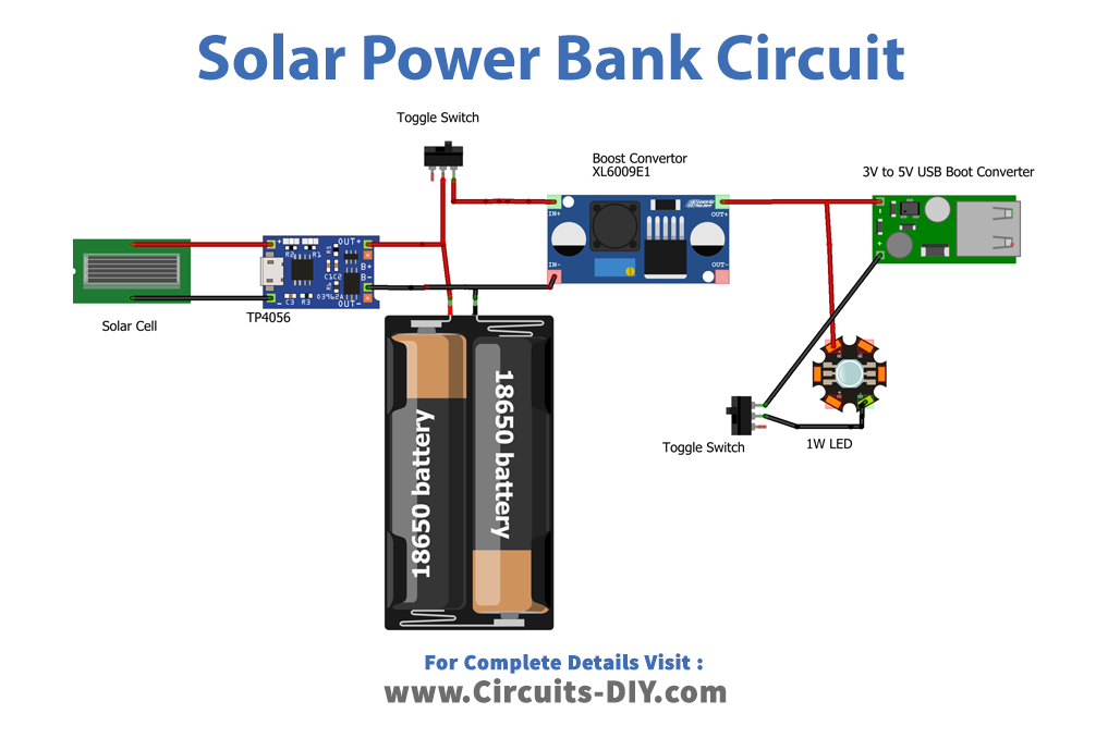
Circuit Diagram
Block Diagram

This block diagram describes the power bank design. The first one is a 5V, 500mA solar panel then a Li-Ion battery charger breakout board TP4056 then two lithium-Ion batteries 18650. Then at the output stage, the XL6009 DC-DC boost converter increases the DC voltage range, 1 Watt white LED is connected to the XL6009 board output through a toggle switch, finally, 3V to 5V USB boost converter breakout board delivers power to mobile or gadgets. Connect the USB to micro-B cable to the output of the boost converter, turn the slide switch ON and the battery of the mobile phone starts to get charged from the power bank. So, this is how you can easily make a power bank circuit for charging your smartphones.
Working Explanation
As we can see in the circuit, first the solar panel +Ve line is connected to the TP4056 Li-Ion battery charger board IN+ terminal and connect -Ve from the solar panel to IN- of TP4056 board, two lithium-ion batteries connected in parallel and then terminals are connected to the BAT+ & BAT- of TP4056 battery charger breakout board. Here lithium cells are available in different capacities corresponding to applications. They are rechargeable cells with 3.7v output. The method of charging a single lithium-ion cell requires two stages, constant current (CC) and constant voltage (CV). During CC the charger should supply constant current with increasing voltage till the voltage limit. Next, a voltage equal to the maximum limit of the cell should be applied during which the current declines steadily to the lower threshold current (i.e., 3% of constant current). All these operations are carried out by the TP4056 module which is a highly reliable and affordable choice. This is a low-cost charging solution to charge any type of single lithium-ion battery. The micro–B receptacle and easily adjustable 1A output current control make it a reliable choice to charge any low-capacity batteries. It can be connected to any wall socket-based mobile charger or any sort of USB to micro-B cable. It is made of an integrated PMOS load switch architecture, hence reducing overall additional components. The module has two indications, Red color LED (L1) to indicate the ongoing charging condition. The blue color LED (L2) indicates the completion of charging. In the last, we have a boost converter, an XL6009 DC-DC converter is capable of giving 5V to 35V output from 3V to 32V input and then gives Non-Isolated boost output. This board is connected to the Li-Ion battery through a toggle switch at the output of the XL 6009 breakout board, a 1-watt white LED and a 3V to 5V USB boost converter are connected.
Now when the solar panel exposes to sunlight it will produce voltage through a photovoltaic reaction and then the boosted voltage from TP4056 makes the Li-Ion battery charge. This charge can be converted into the required voltage by XL6009 and USB boost converter breakout boards. Test the polarity, output voltage, and current at each breakout board and tune it according to your requirements.
Applications
Can be used in any emergency to charge digital electronic devices.