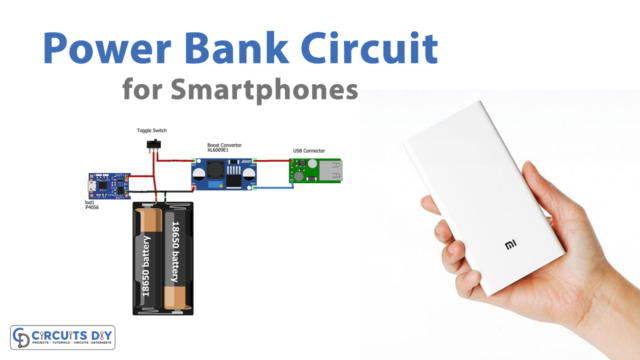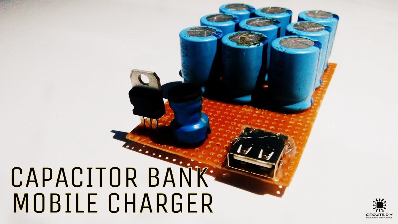
A Power bank is a simple portable battery that uses special circuitry to control any power in & power out. The usage of power banks has increased tenfolds in our daily & it functions as an essential daily driver for many people. Power banks require proper care in terms of preventing overcharge/undercharge & failure to do so can result in your power bank becoming unable to hold a charge. So, in this article, we are going to go over a step-by-step procedure on ‘How How To Make A Power Bank Using Super Capacitor Configuration and a small number of other components.
JLCPCB is the foremost PCB prototype & manufacturing company in china, providing us with the best service we have ever experienced regarding (Quality, Price Service & Time).
Super Capacitor
A supercapacitor is a high-capacity capacitor with ‘C’ values much higher than normal capacitors but with lower voltage limits. They can store 10 to 100 times more energy per unit volume or mass than electrolytic capacitors, can receive and deliver charge much faster than batteries, and tolerate more charging-discharging cycles than rechargeable batteries.
Hardware Components
The following components are required to make Power Bank Project
| S.no | Component | Value | Qty |
|---|---|---|---|
| 1. | Voltage Regulator IC | LM7805 | 1 |
| 2. | Inductor | 50nH | 1 |
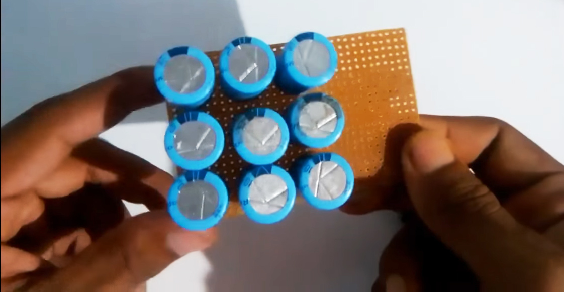
| 3. | Polar Capacitors | 4700uF/10V | 9 |
| 4. | USB Connector Port | Type A | 1 |
| 5. | USB Data Cable | – | 1 |
| 6. | Soldering Iron | 45W-65W | 1 |
| 7. | Soldering wire with Flux | – | 1 |
| 8. | Smartphone | – | 1 |
| 9. | Veroboard | – | 1 |
| 10. | Connecting Wires | – | As per need |
LM7805 Pinout
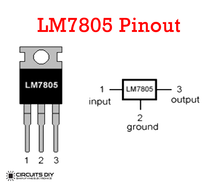
For a detailed description of pinout, dimension features, and specifications download the datasheet of LM7805
Useful Steps
The following are the steps on ‘How To Make A Power Bank Using Super Capacitor’.
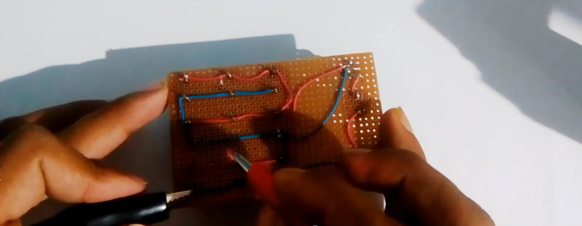
1) Solder all the +ve terminals of the 4700uF Capacitors together with each other & solder all the -ve terminals of the capacitors together as well. (parallel config)
2) Solder the positive terminal of the supercapacitor config to the Vin of the 7805 IC & solder the -ve terminal to the Ground of the IC.
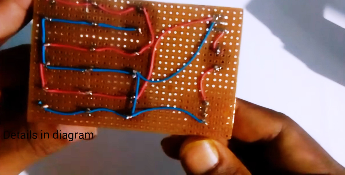
3) Solder a 50nH inductor to the output of the IC.
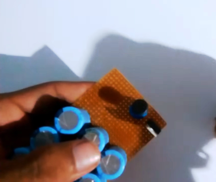
4) Solder the output of the inductor to the pin 1 (Vcc) of the Type a USB port & the -ve terminal of the supercapacitor with the GND pin.
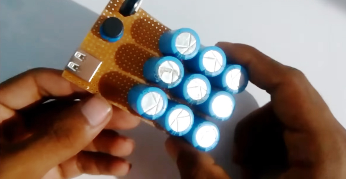
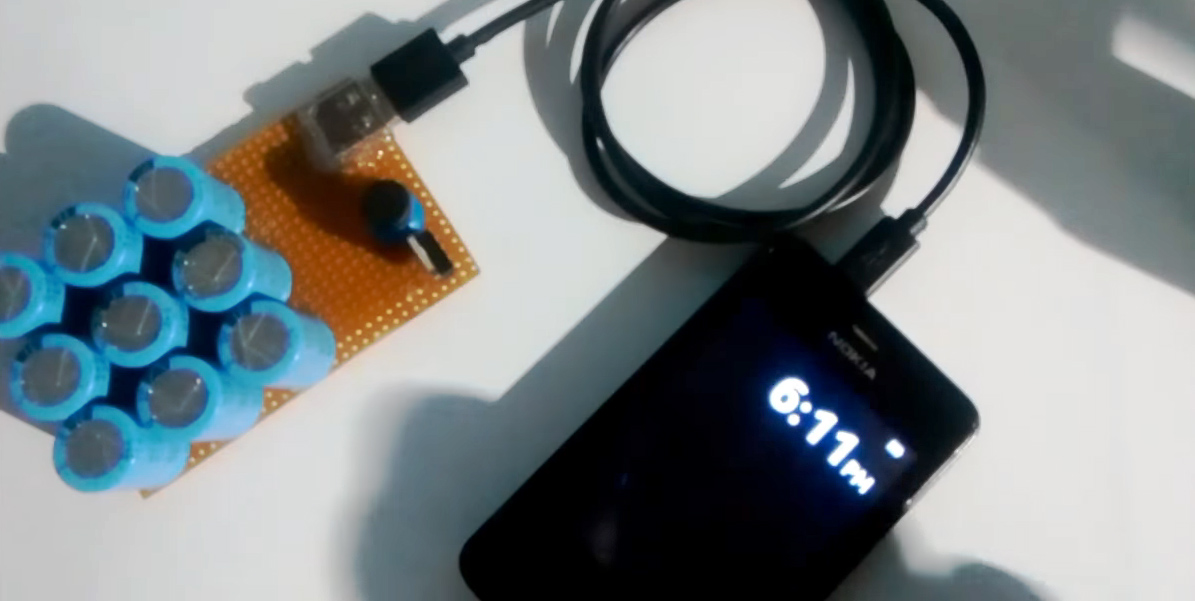
5) Charge the Supercapacitor for 2 sec from a 220V outlet. plug in the smartphone using a USB connector & test the circuit.
Working Explanation
The working of this circuit is very simple, upon charging the parallelly configured supper capacitor circuit, the resultant capacitive voltage is higher than the sum of an individual capacitor voltage. This voltage is then fed to a 7805 IC to produce a DC output with a constant current and voltage.
the output of the regulator is then fed through a 50nh inductor to regulate the current before moving on towards the USB connectors +ve.
Applications
- It can be used to power mobile phones, mp3 players, pacemakers, etc.