In this tutorial, we are developing a “Howland Current Pump Circuit.” The question is, why are we making this circuit? The basic current source isn’t ideal for variable loads as the current through load additionally changes with the load resistance. The answer to this issue is a Constant current source like Howland Current Pump Circuit.
The Howland Current Pump was concocted in 1962 by Professor Bradford Howland from MIT. It comprises an operational amplifier IC and a resistor bridge to keep up the steady current value; however, the heap, regardless of whether the estimation of load resistance changes.
Hardware Components
The following components are required to make the Howland Current Pump Circuit
| S.no | Component | Value | Qty |
|---|---|---|---|
| 1. | Op-amp IC | LM741 | 1 |
| 2. | Resistor | 1K, 3.9K | 3, 2 |
| 3. | Breadboard | – | 1 |
| 4. | Supply | 9 V | 1 |
| 5. | Connecting Wires | – | – |
LM741 Pinout
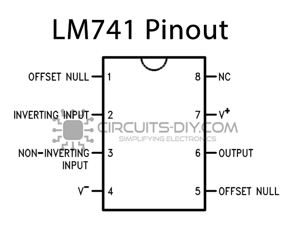
For a detailed description of pinout, dimension features, and specifications download the datasheet of LM741
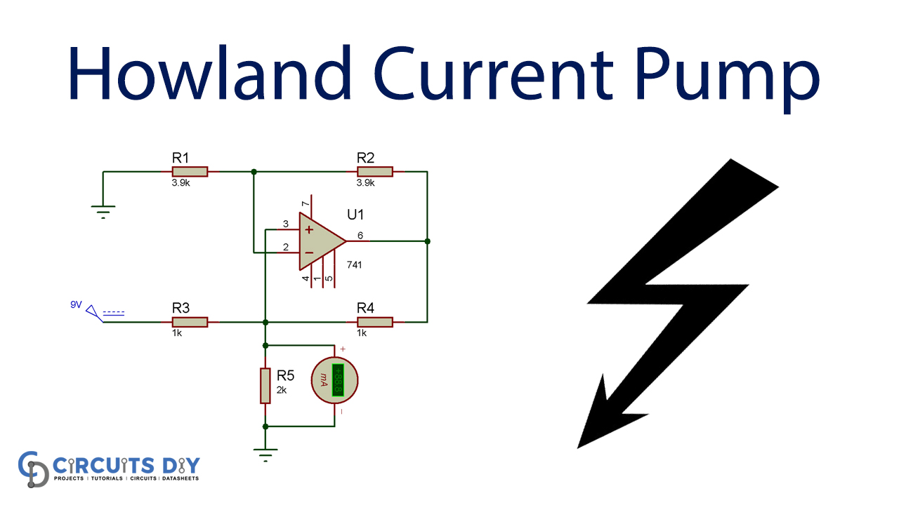
Howland Current Pump Circuit

Circuit Operation
Increasing the value of load resistance often would adjust the voltage through it according to ohm’s law. But an optimal source should keep the current running continuously through the load resistance. The hardware configuration below is for testing the Howland current pump circuit, where RPS supplies the power supply of 9v, but even a 9v battery for testing can be used. In this case, we tested the circuit with a load resistance of 2k and 3.9k and used a wireless multimeter to calculate the power over the cargo. The current stays stable under the two conditions, as seen in the following diagram.


The resistor may also replace active loads like motor or LED.
Applications and Uses
The applications and uses of this project are listed below:
- Biasing diodes and transistors
- Testing other devices
- Production test
- Experimenting