Introduction
Making anything requires tools or equipment to formulate. Whether you’re making food or a house or circuits, everything needs equipment. One cannot work without the tools. It is the most basic need of any project or for any work. This article is all about the basic tools required for making a Printed circuit board.
Tools Required for Printed Circuit Board Designing
All the below-described tools are used by engineers for designing the Printed circuit boards. To understand them all, read the given explanation.
Software for Printed Circuit Board
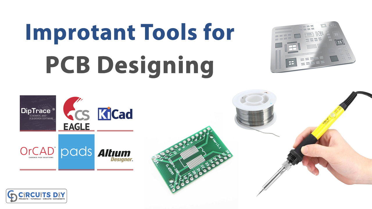
Software is the most crucial tool for designing the schematic, deciding the layers and dimensions, fixing components, routing, etc. There are numerous numbers of software out there in the market. Some efficient software is:
- OrCAD: OrCAD is the most widely used schematic design software. It provides free simulation and components. However, there is a lack of integration of components in one suite. Also, It does the work quickly and does not get clasped. On the other hand, some users find its integration difficult with another database. Moreover, It’s easy to synchronize with its library. Yet according to some designers, it still can improve more.
- Autodesk EAGLE: EAGLE is the abbreviation of Easily Applicable Graphical Layout Editor. It has a schematic capture editor, layout editor, auto-router, and BOM. It makes learning PCB designs easier. It’s user-friendly and cost-effective. And, it is only available on a subscription basis
- PADS: Importantly, this software includes schematic designs, advanced simulation, and analysis. Further, it has constraint management, data management, ECAD-MCAD collaboration, etc
Gerber Files
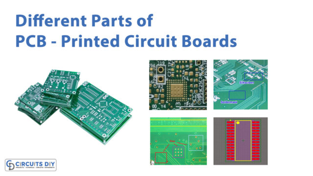
Gerber file plays a major role in the manufacturing process. The Gerber format is a vector image file to describe the images of PCB that is, the layers, solder mask, etc. Also, it had an ASCII text file that had configuration parameters, aperture definition, XY coordinate locations, and draw and flash command codes.
Excellon File
Excellon file is a drill file. It contains information about the hole size, and drill tool numbers on the PCB. Hence, It has the all information about routing and drilling. One can read the Gerber file with several programs available. Some programs are free. While some are not free of cost. You can use Altium Designer to open that Gerber file. However, know that it’s not free of cost.
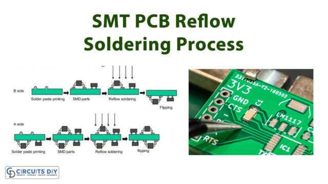
Soldering Machine
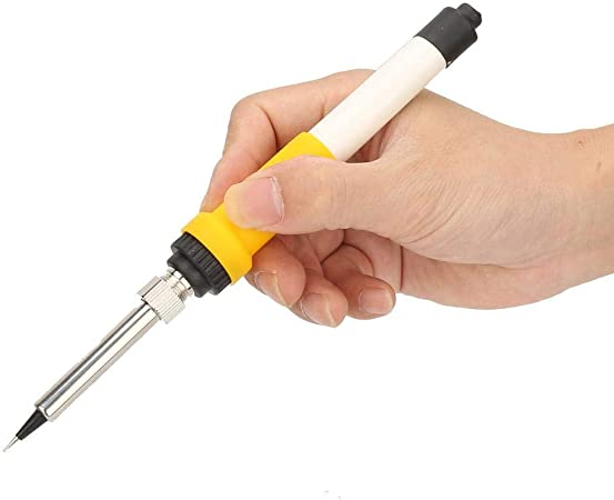
A soldering iron or machine is used to fix the components on the printed circuit board. In addition, it uses a sodering wire to assemble the components to the board.
Stencils for Printed Circuit Board
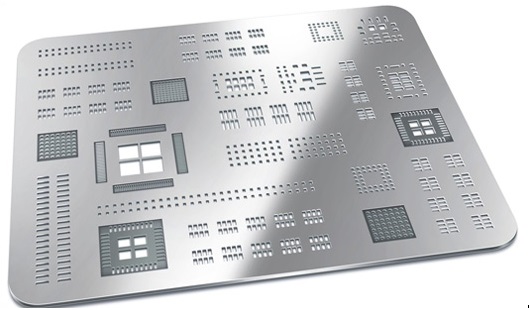
To apply the solder paste on the board stencils show its work. Consequently, it is a stainless foil sheet having laser-cut openings to place a solder paste on the printed circuit board. But, it is usually used for surface mount components. Stencils can be cleaned out with an under-stencil wipe. And, there are various machines to make stencils
Do you make PCBs at Home?
Yeah, using the following tools one can easily make PCBs at home. Yet, it also requires feCl3 powder or solution, photo paper, permanent black marker, sandpaper, cutter, cotton wool, etc. By following the steps intelligently one can make PCB at home very easily