Introduction
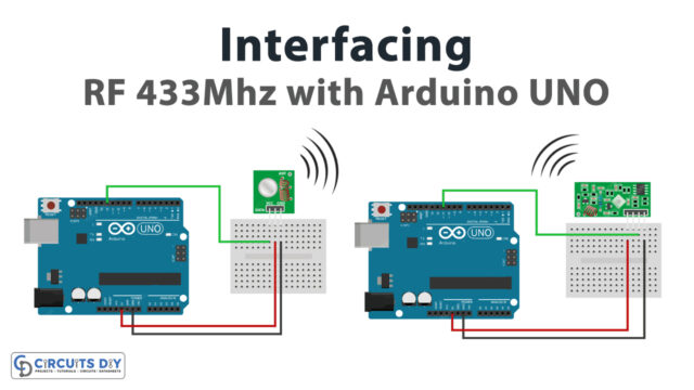
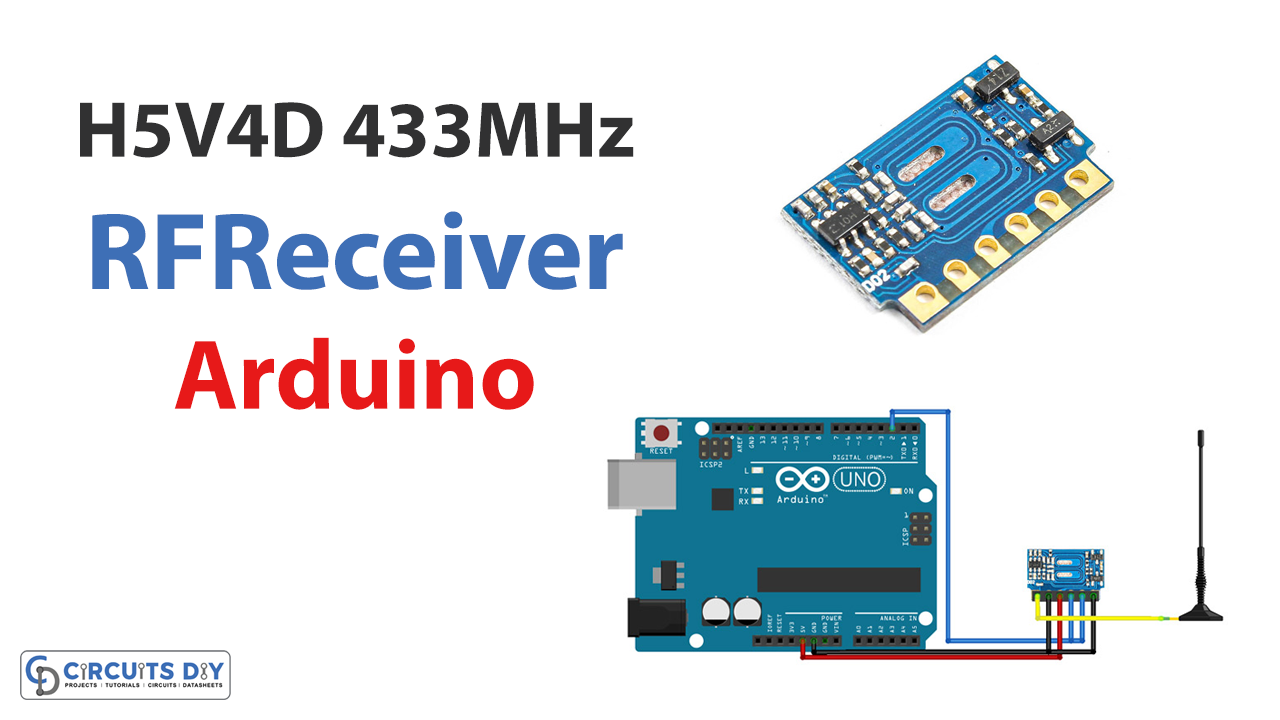
Welcome to the world of wireless communication! Have you ever wanted to remotely control a device or send data over long distances without needing physical cables? If so, the H5V4D 433MHz RF Receiver Module may be what you need. This tiny module can receive signals from a 433 MHz transmitter, allowing you to interact with your Arduino projects in new and exciting ways. So, in this tutorial, we will be interfacing the H5V4D 433MHz RF Receiver Module with Arduino.
Whether you’re building a remote-controlled car or creating a home automation system, the H5V4D module is a versatile and easy-to-use tool that can help bring your ideas to life. So let’s dive in and see how you can use this module to enhance your Arduino projects!
What is a 433MHz RF Receiver Module?
The radio frequency (RF) receiver module is a relatively compact radio frequency (RF) electronic module that can receive radio signals from any device. It is capable of receiving and demodulating radio signals at 433 MHz. The vast majority of wireless communication systems use these modules in their creation.
Hardware Components
You will require the following hardware for Interfacing H5V4D 433MHz RF Receiver Module with Arduino.
| S.no | Component | Value | Qty |
|---|---|---|---|
| 1. | Arduino UNO | – | 1 |
| 2. | Wireless Receiver Module | H5V4D 433MHz | 1 |
| 3. | Breadboard | – | 1 |
| 4. | Jumper Wires | – | 1 |
RF Receiver with Arduino
Interfacing the H5V4D 433MHz RF Receiver Module with Arduino is a simple process that can greatly expand the capabilities of your projects. By following the given steps, you can easily incorporate the module into your Arduino setup and start receiving wireless signals from a transmitter:
Schematic
Make connections according to the circuit diagram given below.
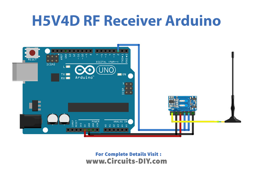
Wiring / Connections
| Arduino | Receiver Module |
|---|---|
| 5V | VCC |
| GND | GND |
| D2 | DATA |
Installing Arduino IDE
First, you need to install Arduino IDE Software from its official website Arduino. Here is a simple step-by-step guide on “How to install Arduino IDE“.
Installing Libraries
Before you start uploading a code, download and unzip the following libraries at /Progam Files(x86)/Arduino/Libraries (default), in order to use the sensor with the Arduino board. Here is a simple step-by-step guide on “How to Add Libraries in Arduino IDE“.
Code
Now copy the following code and upload it to Arduino IDE Software.
/*
  Simple example for receiving

  https://github.com/sui77/rc-switch/
*/

#include <RCSwitch.h>

RCSwitch mySwitch = RCSwitch();

void setup() {
  Serial.begin(9600);
  mySwitch.enableReceive(0);  // Receiver on interrupt 0 => that is pin #2
}

void loop() {
  if (mySwitch.available()) {

    int value = mySwitch.getReceivedValue();

    if (value == 0) {
      Serial.print("Unknown encoding");
    } else {
      Serial.print("Received ");
      Serial.print( mySwitch.getReceivedValue() );
      Serial.print(" / ");
      Serial.print( mySwitch.getReceivedBitlength() );
      Serial.print("bit ");
      Serial.print("Protocol: ");
      Serial.println( mySwitch.getReceivedProtocol() );
    }

    mySwitch.resetAvailable();
  }
}
Let’s Test It
To test the RF Receiver Module, you will need a transmitter operating at 433 MHz. This can be a separate device, such as a remote control or a transmitter module connected to another microcontroller. When the transmitter transmits data, it will send a signal to the RF Receiver Module, which the Arduino sketch will process.
Working Explanation
Let us explore the code to understand the working of the receiver module!
- The code first uses the RCSwitch library to receive signals from a 433MHz transmitter with an Arduino board. The RCSwitch library provides functions that make it easy to receive and decode signals from a transmitter.
- In the setup function, the serial communication is initiated at 9600 baud, and the receiver is enabled on interrupt 0, pin #2 on the Arduino.
- In the loop function, the code checks if a signal is available using mySwitch.available() function. If a signal is available, the code retrieves the received value, bitlength, and protocol using the getReceivedValue(), getReceivedBitlength(), and getReceivedProtocol() functions, respectively. The received value and bitlength are then printed to the serial monitor, along with a message indicating that the signal was received. If the value of the received signal is 0, the encoding is unknown, and an error message is printed.
- Finally, the mySwitch.resetAvailable() function is called to reset the availability of the received signal so that the next signal can be received.
Applications
- Remote control devices and systems.
Conclusion.
We hope you have found this Interfacing H5V4D 433MHz RF Receiver Module with Arduino Circuit very useful. If you feel any difficulty making it feel free to ask anything in the comment section.