Introduction
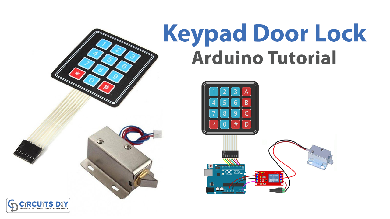
Designing a password-controlled 12V DC electromagnetic lock system using a 4×4 Arduino matrix keypad module and a 5V SPDT relay is a system that combines electronics and programming to build a secure access control system. This system is built using an Arduino UNO microcontroller, which is programmed to receive input from the keypad and control the state of the electromagnetic lock and relay. The system is designed to provide secure access to a restricted area by requiring users to enter a correct password before unlocking the electromagnetic lock. The status of the lock can be monitored and controlled through the serial monitor of the Arduino UNO.
A 4×4 Arduino matrix keypad module is a compact device that consists of 16 buttons arranged in a 4×4 matrix form. These buttons are used to input characters or data into an electronic system. The module typically comes with 8 pins, including 4 columns and 4 rows, which are used to detect the button presses. The module can be interfaced with an Arduino microcontroller, such as the Arduino Uno, by connecting the pins of the module to the digital pins of the microcontroller. The microcontroller then reads the input from the module and processes it according to the programmed logic.
Hardware Components
You will require the following hardware for Interfacing Keypad Door Lock with Arduino.
| S.no | Component | Value | Qty |
|---|---|---|---|
| 1. | Arduino UNO | – | 1 |
| 2. | USB Cable Type A to B | – | 1 |
| 3. | Keypad 3×4 and 4×4 Kit | – | 1 |
| 4. | Relay | – | 1 |
| 5. | Solenoid Lock | – | 1 |
| 6. | Power Adapter | 12V | 1 |
| 7. | DC Power Jack | – | 1 |
| 8. | Power Adapter for Arduino | 9V | 1 |
| 9. | Jumper Wires | – | 1 |
Keypad Door Lock with Arduino
- Start by including the Keypad library, which makes it easier to work with matrix keypads.
#include <Keypad.h>#include <Wire.h>- Define the number of rows and columns on your keypad. In this case, it is a 4×4 keypad.
const int ROW_NUM = 4;
const int COLUMN_NUM = 4;
- Define the keymap of your keypad, which is the mapping of the keys on your keypad to the characters they represent.
char keys[ROW_NUM][COLUMN_NUM] = {
  {'1','2','3','A'},
  {'4','5','6','B'},
  {'7','8','9','C'},
  {'*','0','#','D'}
};
- Specify the pins for each row and column of the keypad.
byte pin_rows[ROW_NUM] = {9, 8, 7, 6};
byte pin_column[COLUMN_NUM] = {5, 4, 3, 2};
- Create a Keypad object using the
makeKeymapfunction and the pins for the rows and columns.
Keypad keypad = Keypad( makeKeymap(keys), pin_rows, pin_column, ROW_NUM, COLUMN_NUM );
- In the setup function, start the serial communication at a 9600 baud rate.
void setup(){
  Serial.begin(9600);
}
- In the loop function, read the keypad and store the pressed key in a variable.
void loop(){
  char key = keypad.getKey();
  ...
- Check if a key is pressed and compare it to the password. If the password is correct, set the relay pin to
HIGHunlock the electromagnetic lock. If the password is incorrect, set the relay pin to LOW and keep the lock locked.
  ...
  if (key){
    if (key == '#'){
      if (password == "1234"){
        digitalWrite(relayPin, HIGH);
        Serial.println("Unlocked");
      } else {
        digitalWrite(relayPin, LOW);
        Serial.println("Wrong password");
      }
      password = "";
    } else {
      password += key;
      Serial.println(password);
    }
  }
}
Schematic
Make connections according to the circuit diagram given below.
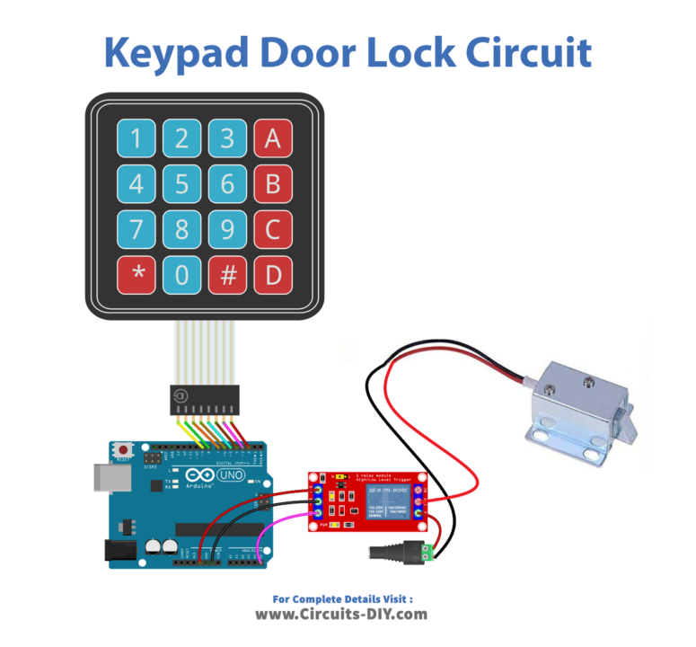
Wiring / Connections
| Arduino | Relay | 4X4 Keypad |
|---|---|---|
| 5V | VCC | |
| GND | GND | |
| A0 | INP | |
| D2 | R1 | |
| D3 | R2 | |
| D4 | R3 | |
| D5 | R4 | |
| D6 | C1 | |
| D7 | C2 | |
| D8 | C3 | |
| D9 | C4 |
Installing Arduino IDE
First, you need to install Arduino IDE Software from its official website Arduino. Here is a simple step-by-step guide on “How to install Arduino IDE“.
Installing Libraries
Before you start uploading a code, download and unzip the following libraries at /Progam Files(x86)/Arduino/Libraries (default), in order to use the sensor with the Arduino board. Here is a simple step-by-step guide on “How to Add Libraries in Arduino IDE“.
Code
Now copy the following code and upload it to Arduino IDE Software.
#include <Keypad.h>

const int RELAY_PIN  = A5; // the Arduino pin, which connects to the IN pin of relay
const int ROW_NUM    = 4; // four rows
const int COLUMN_NUM = 4; // four columns

char keys[ROW_NUM][COLUMN_NUM] = {
  {'1','2','3', 'A'},
  {'4','5','6', 'B'},
  {'7','8','9', 'C'},
  {'*','0','#', 'D'}
};

byte pin_rows[ROW_NUM] = {9, 8, 7, 6}; //connect to the row pinouts of the keypad
byte pin_column[COLUMN_NUM] = {5, 4, 3, 2}; //connect to the column pinouts of the keypad

Keypad keypad = Keypad( makeKeymap(keys), pin_rows, pin_column, ROW_NUM, COLUMN_NUM );

const String password_1 = "1234ABC"; // change your password here
const String password_2 = "5642CD";  // change your password here
const String password_3 = "4545B";   // change your password here
String input_password;

void setup() {
  Serial.begin(9600);
  input_password.reserve(32); // maximum input characters is 33, change if needed
  pinMode(RELAY_PIN, OUTPUT); // initialize pin as an output.
  digitalWrite(RELAY_PIN, LOW); // lock the door
}

void loop() {
  char key = keypad.getKey();

  if (key){
    Serial.println(key);

    if(key == '*') {
      input_password = ""; // reset the input password
    } else if(key == '#') {
      if(input_password == password_1 || input_password == password_2 || input_password == password_3) {
        Serial.println("The password is correct, unlocking the door in 20 seconds");
        digitalWrite(RELAY_PIN, HIGH);  // unlock the door for 20 seconds
        delay(20000);
        digitalWrite(RELAY_PIN, LOW); // lock the door
      } else {
        Serial.println("The password is incorrect, try again");
      }

      input_password = ""; // reset the input password
    } else {
      input_password += key; // append new character to input password string
    }
  }
}
Working Explanation
The setup() function in the above code initializes the serial communication at a 9600 baud rate and sets the pin used to control the relay as an output. It also initializes the input password string and locks the door by setting the relay pin to LOW.
The loop() the function runs continuously after the setup() has been executed. It waits for a key press on the keypad and if a key is pressed, it retrieves the key value and prints it to the serial monitor. If the key is ‘*’, the input password string is reset. If the key is ‘#’, the code checks if the input password matches one of the predefined passwords. If a match is found, it prints a message to the serial monitor, unlocks the door for 20 seconds by setting the relay pin to HIGH, then locks the door again by setting the relay pin to LOW. If no match is found, it prints an error message to the serial monitor. Regardless of whether a match is found or not, the input password string is reset.
Applications
- Security systems
- Access control systems
- Door locks
- Electronic safes and cabinets
- Automated teller machines (ATMs)
- Personal identification number (PIN) verification
- Time and attendance systems
- Electronic voting systems
- Electronic keyless door locks
Conclusion.
We hope you have found this Keypad Door Lock Arduino Circuit very useful. If you feel any difficulty in making it feel free to ask anything in the comment section.