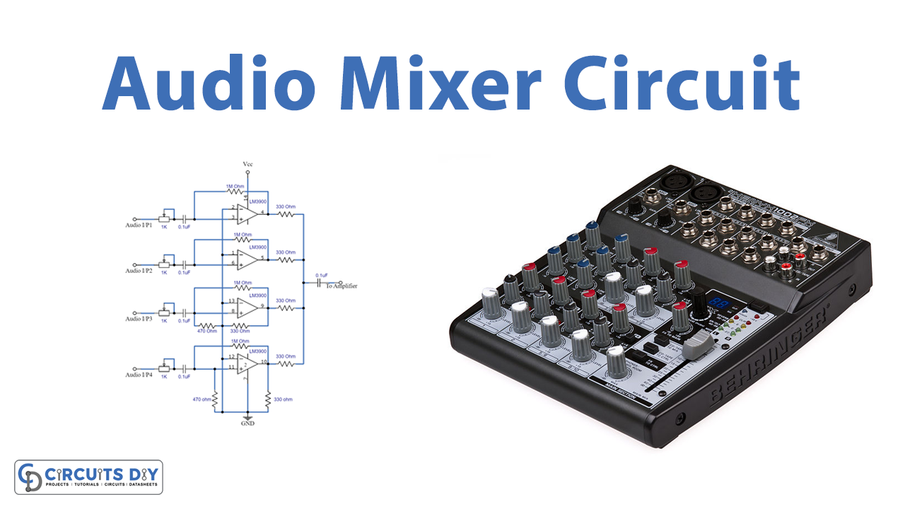
In this tutorial, we are going to make an “LM3900 Audio Mixer Circuit”. An audio mixer circuit is used to combine output from several microphones/channels into one or more common outputs. Often, you’ll find audio mixers in either digital or analog form. Analog mixers incorporate op-amp integrated circuits, while the digital type uses a digital signal processing technology. Usually, this circuit is used for public address purposes or while recording. The main goal of the audio mixture, as the name suggests is to ‘mix’ the different audio signals which are fed to the input for the mixer. As we need an audio mixer to amplify multiple and different audio inputs with a single amplifier.
Here we design a simple audio mixer circuit by using IC LM3900, it is a Quadruple Norton operational amplifier that comes with 14 pins Dual inline package. The LM3900 operates with a wide range of supply voltages (4.5V to 32V) and has internal frequency compensation. We can mix and amplify four different audio inputs by using this circuit. Here variable resistors VR1 – VR4 are used to vary individual audio input gain. The circuit has two channels for microphone inputs and two channels for inputs from other devices. If you want a mixer with more input channels, you can duplicate this circuit and get a mixer with up to 8 channels.
Hardware Required
| S.no | Component | Value | Qty |
|---|---|---|---|
| 1. | IC | LM3900 | 4 |
| 2. | Variable Resistor | 1KΩ | 4 |
| 3. | Resistor | 330Ω,470Ω,1MΩ | 6,2,4 |
| 4. | Capacitor | 0.1uf | 5 |
| 5. | Connecting Wires | – | – |
| 6. | Power Supply | 32V | 1 |
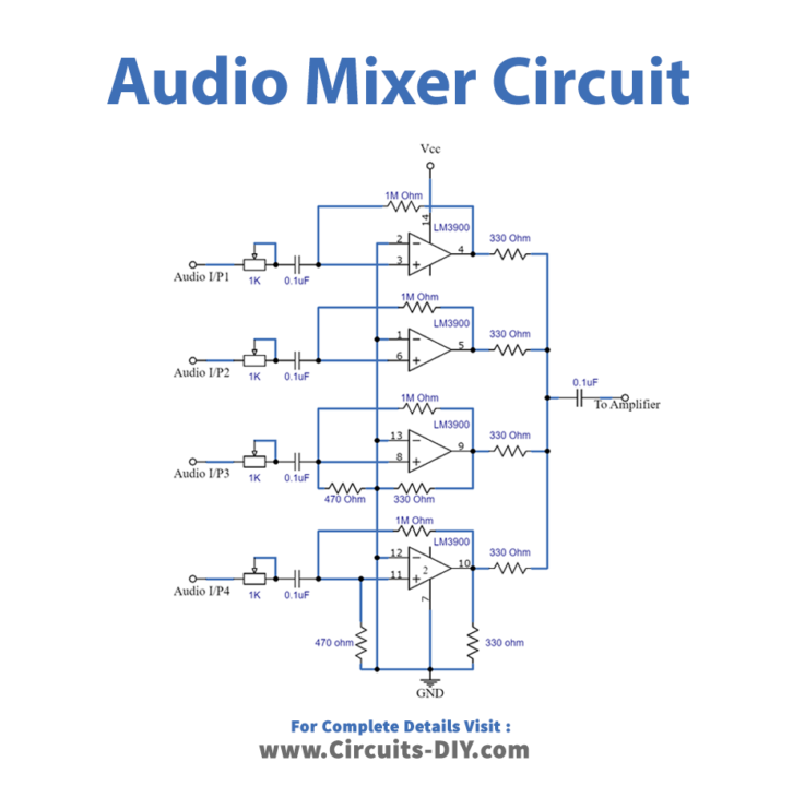
Circuit Diagram
IC LM3900
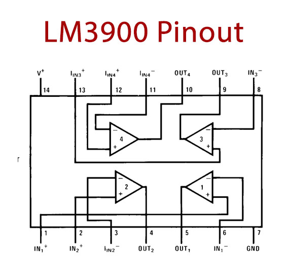
It has 14 pins for four internal operational amplifiers, each amplifier will have inverting, non-inverting, and output pins. And power supply pins Vcc and Gnd are common to all internal amplifiers. Four internal amplifiers in LM3900 work independently with high gain frequency compensation. It requires only one power supply source and also it can operate with a split supply (You can use voltage sources of +32 volts maximum or dual +/- 16 volts maximum). It has features like high amplitude output voltage, low noise, and large bandwidth, which allows for amplifying audio signals without problems. And large output voltage swing.
Working Explanation
The main stage in this audio mixer circuit is the amplifier stage and here LM3900 IC is used as an amplifier. All operational amplifiers are configured as inverting amplifiers (Inverting input of the amplifier gets the audio signals and non-inverting pins are grounded) and have decoupling capacitors at their inputs and outputs. These capacitors filter (block) the direct current component of the signals at the input and output, amplifying only the alternating signal (the audio signal). For feedback setup, a 1M resistor is used for all stages. All internal amplifiers (A1-A4) are employed to amplify the audio input signals. Op-amps A1 and A2 each have two resistors: R1, R12, and R2, R11. However, op-amps A3 and A4 each have four resistors: R3, R10, R4, R5, and R6, R9, R7, and R8. Here each audio input is controlled by variable resistors (VR1 – VR4 placed at the inverting input of each amplifier). Each variable resistor controls the audio level of each channel before amplifying the signal and performing the audio mix. The outputs of the 4 channels are mixed after passing through 4 resistors of the same value (R11, R12, R13, and R14). Finally, the output signals are combined for the external power amplifier. As this audio mixer circuit requires a regulated DC power supply and audio signals can be directly given as input or can be given after pre-amplification. Therefore provides common ground (GND) for all non-inverting inputs. And instead of variable resistors, we can use a sliding adjustable potentiometer to make the circuit more professional. This circuit will give only a mixed audio output signal with minimum gain, but you can use an external amplifier to strengthen the audio output signal.
Applications
The audio mixer circuits can be used on both the recording and playback sides.