Overview
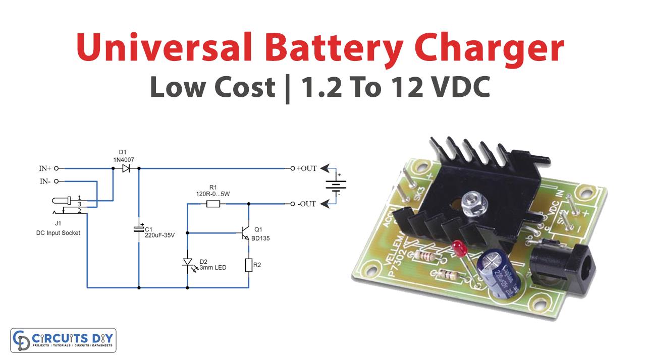
In today’s tutorial, we are going to make a “Universal Battery Charger Circuit” using a BD135 transistor.
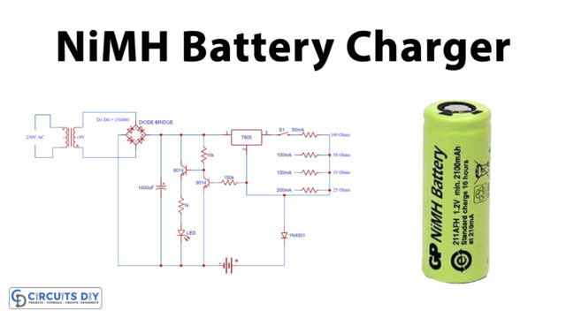
Here is the schematic of an affordable universal battery charger designed specifically for NiCD and NiMH batteries. This circuit is particularly suitable for use in cars. It can convert a standard mains adapter into a versatile charger, capable of charging a variety of devices such as cellular phones, toys, portables, video batteries, and MP3 players. The charger offers selectable charge currents and features an LED indicator to show the charging status. It can be easily assembled on a general-purpose PCB or a veroboard. We believe you will find this circuit highly useful and convenient for your charging needs.
Universal Battery Charger?
A universal battery charger refers to a device or circuit designed to charge multiple types and sizes of rechargeable batteries. These chargers are versatile and can typically handle various battery chemistries such as lithium-ion (Li-ion), nickel-cadmium (NiCd), nickel-metal hydride (NiMH), and others
Hardware Components
To make a universal battery charger, you’ll need the following hardware components to get started:
| S.no | Components | Value | Qty |
|---|---|---|---|
| 1 | Transistors | Q1 = BD135 | 1 |
| 2 | Polar Capacitors | C1 = 220uF-35V | 1 |
| 3 | Diodes | D1 = 1N4007 | 1 |
| 4 | Resistors | R1 = 120R-0…5W R2 = See diagram | 1 1 |
| 5 | LEDs | 3mm | 1 |
| 6 | Jumper wire | J1 = DC Input Socket | 1 |
Schematic
Specifications:
- Ideal for in-car use.
- LED charge indication.
- Selectable charge current.
- Charges Ni Cd or NiMH batteries.
- Transforms a mains adapter into a charger.
- Charge cellular phones, toys, portables, video batteries …
Features:
- LED function indication.
- Power supply polarity protected.
- Supply current: same as charge current.
- Supply voltage: from 6.5VDC to 21VDC (depending on used battery)
- Charge current (±20%): 50mA, 100mA, 200mA, 300mA, 400mA. (selectable)
Determining the supply voltage:
This table indicates the minimum and maximum voltages to supply the charger. See the supply voltage selection chart below.
To charge a 6V battery a minimum supply voltage of 12V is needed, the maximum voltage is then 15V.

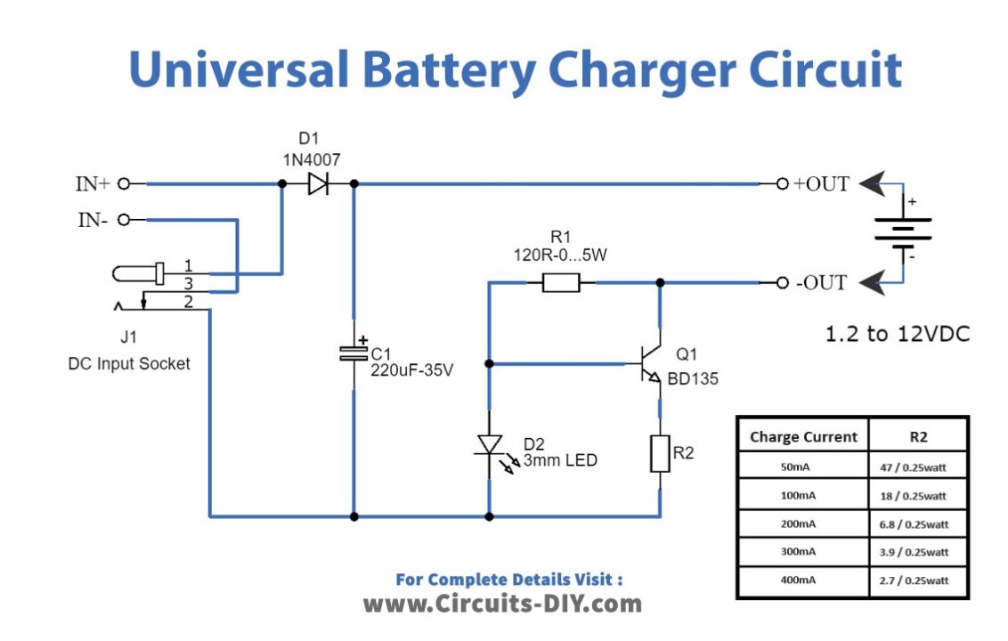
Determining the charge current:
Before building the circuit, you must determine how much current will be used to charge the battery or battery pack. It is advisable to charge the battery with a current that is 10 times smaller than the battery capacity and to charge it for about 15 hours. If you double the charge current, then you can charge the battery in half the time. The charge current selection chart is located in the diagram.
A battery pack of 6V / 1000mAh can be charged with 100mA during 15 hours. If you want to charge faster, then a charge current of 200mA can be used for about 7 hours.
Caution:
The higher the charge current, the more critical the charge time must be checked. When faster charging is used, it is advisable to discharge the battery completely before charging. Using a charge current of 1/10 of the capacity will expand the lifetime of the battery. The charge time can easily be doubled without damaging the battery.
Note:
Mount the transistor together with the heatsink on the PCB, and bend the leads as necessary. Take care that the metal back of the transistor touches the heatsink. Check that the leads of the transistor do not touch the heatsink.
Conclusion
The low-cost universal battery charger circuit presented in this article offers a versatile and efficient solution for charging NiCD and NiMH batteries. Its ability to transform a mains adapter into a charger makes it ideal for car use and various portable devices