Overview
In today’s era of technology, the Internet of Things (IoT) has opened the doors to innovative solutions in various fields. One such application is an object counter that utilizes Infrared (IR) sensors in conjunction with the XIAO RP2040 microcontroller board, offering a smart and efficient way to count objects passing through a specific area. Whether for inventory management, traffic monitoring, or other purposes, this system provides a versatile and cost-effective solution.
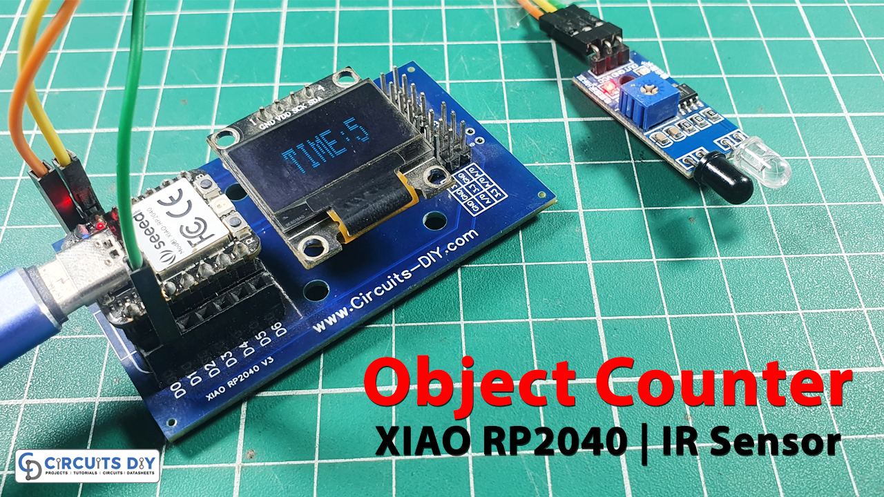
In today’s tutorial, we are going to make an “Object Counter” using the XIAO RP2040 Microcontroller & OLED SSD1306.
What is an Object Counter?
An object counter is a device or system designed to count the number of objects passing through a specific area or point. It utilizes various sensors or technologies to detect the presence of an object and increment a count accordingly.
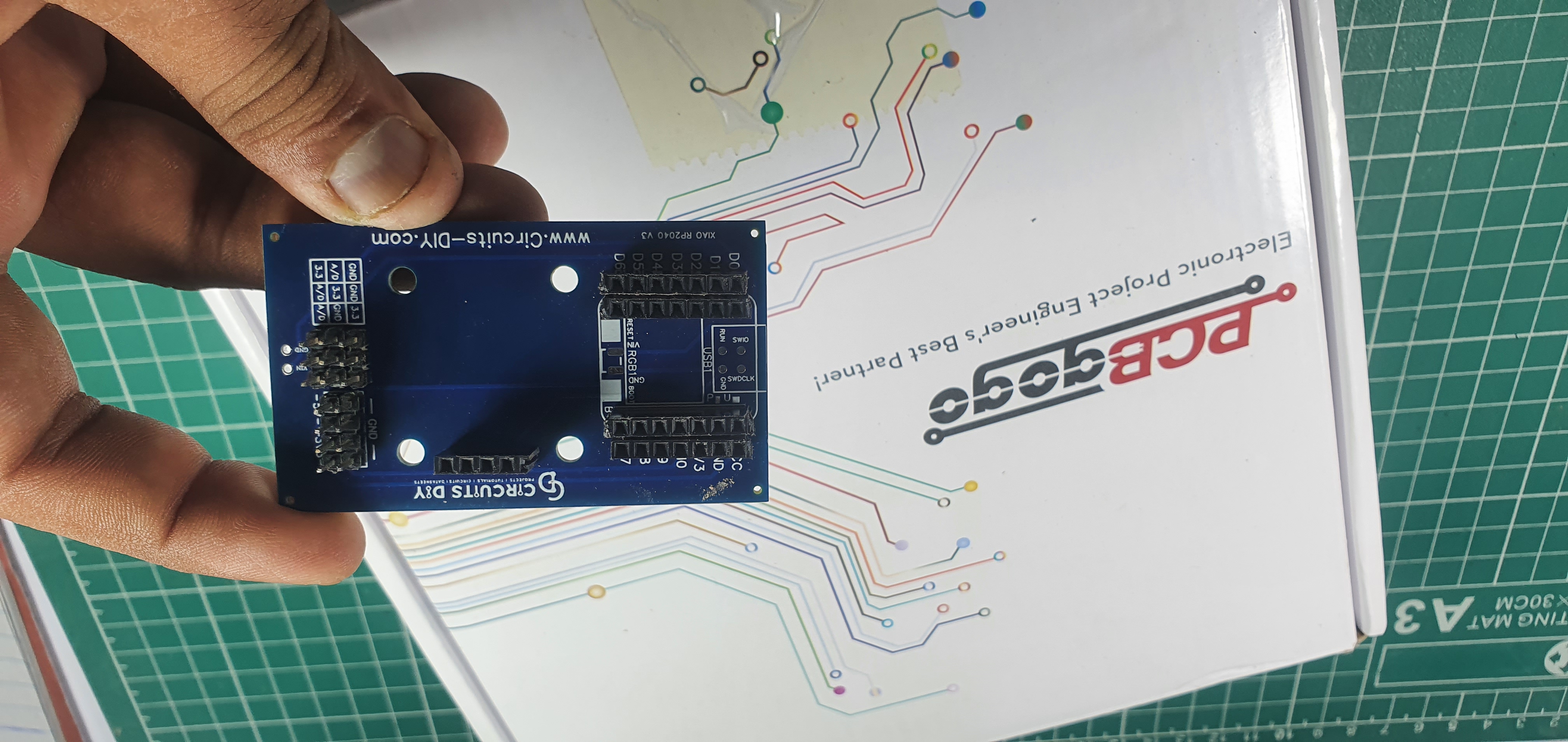
PCBGOGO has offered high-quality PCBs and the best PCB assembly service all over the world since 2015. Discover an incredible offer that puts PCB prototyping within reach for just $1. Yes, you read that right – for only a dollar, you can bring your innovative ideas to life with a PCB prototype. Don’t miss out on this fantastic opportunity to turn your electronics projects into reality. Explore the campaign here: PCBGOGO $1 PCB Prototype and pave the way for your next big creation!
Hardware Components
You’ll need the following hardware components to get started:
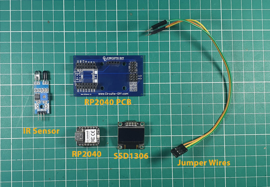
| Components | Value / Model | Qty |
|---|---|---|
| PCB | PCB-GOGO | |
| XIAO | RP2040 | 1 |
| OLED Display Module | SSD1306 | 1 |
| IR Sensor | – | 1 |
| Jumper Wires | – | 1 |
XIAO RP2040 Pinout
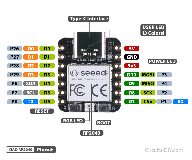
For details on the datasheet of the XIAO RP2040 Microcontroller visit this link.
| Pin No | Pin Name |
|---|---|
| 1 | P26 / A0 / D0 |
| 2 | P27 / A1 / D1 |
| 3 | P28 / A2 / D2 |
| 4 | P29 / A3 / D3 |
| 5 | P6 / SDA/ D4 |
| 6 | P7 / SCL / D5 |
| 7 | P0 / TX / D6 |
| 8 | P1 / RX / CSN / D7 |
| 9 | P2 / SCK / D8 |
| 10 | P3 / MISO / D9 |
| 11 | P4 / MOSI / D10 |
| 12 | 3V3 |
| 13 | GND |
| 14 | 5V |
SSD1306 OLED Display Pinout
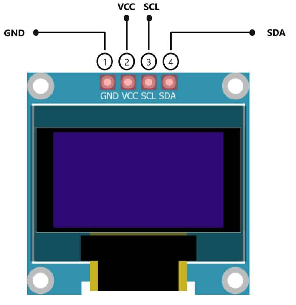
For details, on the datasheet of SSD1306 OLED Display Pinout visit this link.
| Pin No | Pin Name | Pin Description |
|---|---|---|
| 1 | VCC | VCC is the +5 volt Positive Pin |
| 2 | GND | GND is the (Ground) Negative |
| 3 | SCL | SCL is the Serial Clock Pin |
| 4 | SDA | SDA is the Serial Data Pin |
Steps-by-Step Guide
(1) Setting up Arduino IDE
Download Arduino IDE Software from its official site. Here is a step-by-step guide on “How to install Arduino IDE“.
(2) XIAO RP2040 in Arduino IDE
There’s an add-on that allows you to program the XIAO RP2040 using the Arduino IDE. Here is a step-by-step guide on “How to Install XIAO RP2040 on Arduino IDE“.
(3) Include Libraries
Before you start uploading a code, download and unzip the Wire.h, Adafruit_GFX.h, Adafruit_SSD1306.h library at /Program Files(x86)/Arduino/Libraries (default). Here is a step-by-step guide on “How to Add Libraries in Arduino IDE“.
(4) Schematic
Make connections according to the circuit diagram given below.
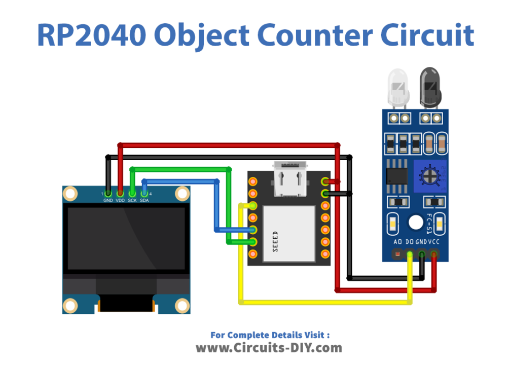
Wiring / Connections
| XIAO RP2040 | SSD1306 OLED Display | IR Sensor |
|---|---|---|
| 5V | VCC | VCC |
| GND | GND | GND |
| A5 | SCK | – |
| A4 | SDA | – |
| D2 | – | DOUT |
(5) Uploading Code
Now copy the following code and upload it to Arduino IDE Software.
// Circuits DIY
// For Complete Details Visit -> https://www.circuits-diy.com/object-counter-using-ir-sensor-xiao-rp2040/

#include <Wire.h>
#include <Adafruit_GFX.h>
#include <Adafruit_SSD1306.h>

#define OLED_RESET 4
Adafruit_SSD1306 display(OLED_RESET);

int IR_pin = D2;  // digital input pin for IR sensor
int counter = 0; // initialize counter to 0

void setup() {
  pinMode(IR_pin, INPUT);
  Serial.begin(9600);
  display.begin(SSD1306_SWITCHCAPVCC, 0x3C);
  display.clearDisplay();
  display.setTextColor(WHITE);
  display.setTextSize(2);
  display.setCursor(0, 10);
  display.print("STOP WATCH");
  display.display();
  delay(2000);
}

void loop() {
  if (digitalRead(IR_pin) == LOW) { // object detected
    counter++; // increment counter
    display.clearDisplay();
    display.setTextSize(2);
    display.setCursor(30, 10);
    display.print("TIME:");
    display.print(counter);
    display.display();
    Serial.println(counter); // print counter value to serial monitor
    delay(500); // delay to debounce sensor
  }
}
How code works
#include <Wire.h>
#include <Adafruit_GFX.h>
#include <Adafruit_SSD1306.h>
This code includes the necessary libraries required for interfacing with the OLED display. The Wire.h library is for I2C communication, Adafruit_GFX.h provides graphics functions, and Adafruit_SSD1306.h is for controlling the SSD1306-based OLED display.
#define OLED_RESET 4
Adafruit_SSD1306 display(OLED_RESET);

int IR_pin = D2;  // digital input pin for IR sensor
int counter = 0; // initialize counter to 0OLED_RESETis defined as pin 4, used to reset the OLED display.Adafruit_SSD1306 display(OLED_RESET);initializes the SSD1306 display using the defined reset pin.IR_pinis assigned the value of pin D2, which is the digital input pin connected to the IR sensor.counteris initialized as an integer variable with an initial value of 0 to keep track of the count.
void setup() {
  pinMode(IR_pin, INPUT);
  Serial.begin(9600);
  display.begin(SSD1306_SWITCHCAPVCC, 0x3C);
  display.clearDisplay();
  display.setTextColor(WHITE);
  display.setTextSize(2);
  display.setCursor(0, 10);
  display.print("STOP WATCH");
  display.display();
  delay(2000);
}
pinMode(IR_pin, INPUT);sets the IR_pin as an input pin to receive signals from the IR sensor.Serial.begin(9600);initializes serial communication at a baud rate of 9600 for debugging or output.display.begin(SSD1306_SWITCHCAPVCC, 0x3C);initializes the OLED display with specific settings.- Display setup commands:
display.clearDisplay();clears the display.display.setTextColor(WHITE);sets the text color to white.display.setTextSize(2);sets the text size to 2x.display.setCursor(0, 10);sets the starting position for text.display.print("STOP WATCH");prints “STOP WATCH” on the OLED display.display.display();displays the content on the OLED.delay(2000);creates a delay of 2 seconds to show the “STOP WATCH” message for a brief time.
void loop() {
  if (digitalRead(IR_pin) == LOW) { // object detected
    counter++; // increment counter
    display.clearDisplay();
    display.setTextSize(2);
    display.setCursor(30, 10);
    display.print("TIME:");
    display.print(counter);
    display.display();
    Serial.println(counter); // print counter value to serial monitor
    delay(500); // delay to debounce sensor
  }
}
digitalRead(IR_pin) == LOWchecks if the IR sensor input is LOW (object detected).- Inside the if statement:
counter++;increments the counter by one.- OLED display commands:
display.clearDisplay();clears the display.display.setTextSize(2);sets the text size to 2x.display.setCursor(30, 10);sets the starting position for text.display.print("TIME:");prints “TIME:” on the OLED display.display.print(counter);prints the current counter value on the OLED display.display.display();displays the updated content on the OLED.
Serial.println(counter);prints the counter value to the serial monitor for debugging or monitoring purposes.delay(500);introduces a delay of 500 milliseconds to debounce the sensor, preventing multiple counts for a single object detection event.
This code essentially creates an object counter using an IR sensor connected to a microcontroller RP2040 and displays the count on an OLED screen while also printing the count to the serial monitor.
Applications
- Retail: Counting the number of customers entering a store to track foot traffic.
- Manufacturing: Keeping track of the number of items produced on an assembly line.
- Traffic Monitoring: Counting vehicles or pedestrians passing through specific points on roads or walkways.
- Inventory Management: Tracking the movement of items in warehouses or storage facilities.
- Event Attendance: Monitoring the number of people entering or leaving an event venue.
Conclusion
An object counter using IR sensors and the XIAO RP2040 microcontroller board provide a simple yet effective solution for counting objects in various scenarios. This system can be further enhanced by incorporating additional features like data logging, integration with cloud services for remote monitoring, or combining it with other sensors for more advanced functionalities