Generally speaking, PCBs or Printed Circuit boards are a complex mass of insulators and copper traces that connect dense components to create a modern circuit. PCB troubleshooting is often a challenge for hobbyists & beginner to electronics, & one can easily feel lost in figuring out where to begin. So in today’s tutorial, we are going to discuss the top 5 PCB troubleshooting tips & techniques you can use today to step up your design game.
Troubleshooting PCBs is often a challenge, with factors such as size, number of layers, signal analysis, and types of components playing a large role. But there are a number of methods & practices that you can use to ensure a systematic approach to troubleshooting PCBs.
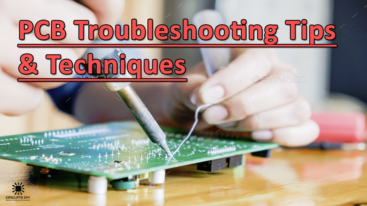
PCB Troubleshooting Tips & Techniques
1) Get the Right Tools for the Job
Make sure that you have the right tools available to help you with your troubleshooting. This includes tools ranging from basic tools such as multimeters, test probes, continuity testers & wire cutters, to advance tools such as LCR meter, oscilloscope, power supply, and logic analyzer.
2) Visual Inspection First!
Perform a thorough visual inspection of the PCB before getting on with the troubleshooting process. This will help you in determining defects such as overlapped traces, burnt out components, signs of overheating, missing & bulging components.
3) Perform a Physical Inspection
Power up the PCB & perform a physical inspection. Search for hot spots by either lightly touching the surface of the PCB or by simply using a thermal camera. On finding a hot part, cool it down with short blasts of canned air & test the circuit operation with the affected part at lower temperatures. While touching a live circuit, make sure that only one hand makes actual contact with the PCB board in order to prevent a fatal electrical shock from traveling through your heart.
4) Discrete Component Testing
Test the health of every discrete component on the PCB board. Using an AVO/LCR meter, Test each resistor, capacitor, diode, transistor, inductor, MOSFET & LEDs. If any part shows less than or equal to the actual component value, the parts are typically good. If the value of the part is higher, it’s an indication that either the actual part is bad or the solder joint is bad.
5) Conduct IC Testing
Check every IC on the PCB board for anomalous behavior using a logic analyzer & an oscilloscope. Keep an eye out for any operational discrepancies. Most ICs can be easily identified by the markings present on top the IC cover.
So by using the above PCB debugging tips, you can take your PCB design skills to the next level.