In this tutorial, we are going to Interface an “AD8232 ECG Module with Arduino”
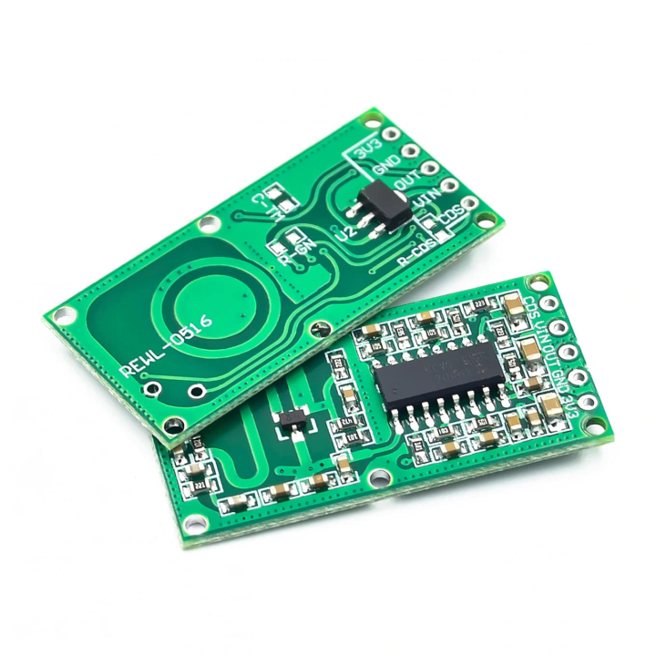
RCWL0516 Microwave Distance Sensor Module
As an alternative to the typical PIR motion sensors frequently seen in burglar alarms and security lights, the RCWL0516 Microwave Distance Sensor Module has been designed. This sensor, like that of the PIR Sensor, only picks up movement that is within its detecting range. However, this sensor uses a “microwave Doppler radar” approach to find moving objects rather than sensing the blackbody radiation from a passing human.
Hardware Overview
- Power supply pins and input/output (i/o) pin connections to microcontrollers and other electronic components are located in the input/output block.
- The system that implements the Doppler effect technology is the RCLW0516 IC, which is less error-prone than PIR.
- A built-in antenna to catch the incoming waves and an amplifier to amplify the radio signals emanating from the module.
- NPN transistors, capacitors, and an inductor all work together to create oscillations at a certain high frequency. It functions as a Colpitts oscillator, to put it simply. The decoupling and filtering of signals are other functions carried out by the capacitors.
- There is a CDS pin to attach a light resistor to the module so that it can only function in complete darkness. It serves as an enable/disable control as well.
Thus, the module includes all of the necessary components as well as a single transistor-based high-frequency oscillator that creates a microwave signal with a frequency of roughly 3.175GHz, a wavelength of 9.45cm, and a half wavelength of 4.725cm. There is additionally a power LED that indicates the module’s power condition.
Working Principle
After processing the signal, the chip’s internal circuitry generates an analog voltage in proportion to the distance between the object and the sensor. The integrated antenna both receives and produces microwave transmissions. The mixer/amplifier receives a signal that is reflected by the antenna and transmits it there. It combines the transmitted and reflected signals before sending the difference to the IC for processing. The IC will transmit an output voltage signal that will display how close the body is to the sensor in relation to that voltage. The RCWL0516 Microwave Distance Sensor, one could say, employs microwave frequencies in a conventional Doppler radar system.
Pinouts
| Pin Number | Pin Name | Description |
|---|---|---|
| 1 | 3V3 | Regulated 3.3V output |
| 2 | GND | Ground reference |
| 3 | OUT | The analog output from the sensor |
| 4 | VIN | The voltage input for the module |
| 5 | CDS | Sensor Disable |
Hardware Required
| Sr. No | Components | Value | Qty |
|---|---|---|---|
| 1 | Arduino | UNO | 1 |
| 2 | USB Cable | Type A to B | 1 |
| 3 | Microwave Radar Sensor Module | RCWL0516 | 1 |
| 4 | Jumper Wires | – |
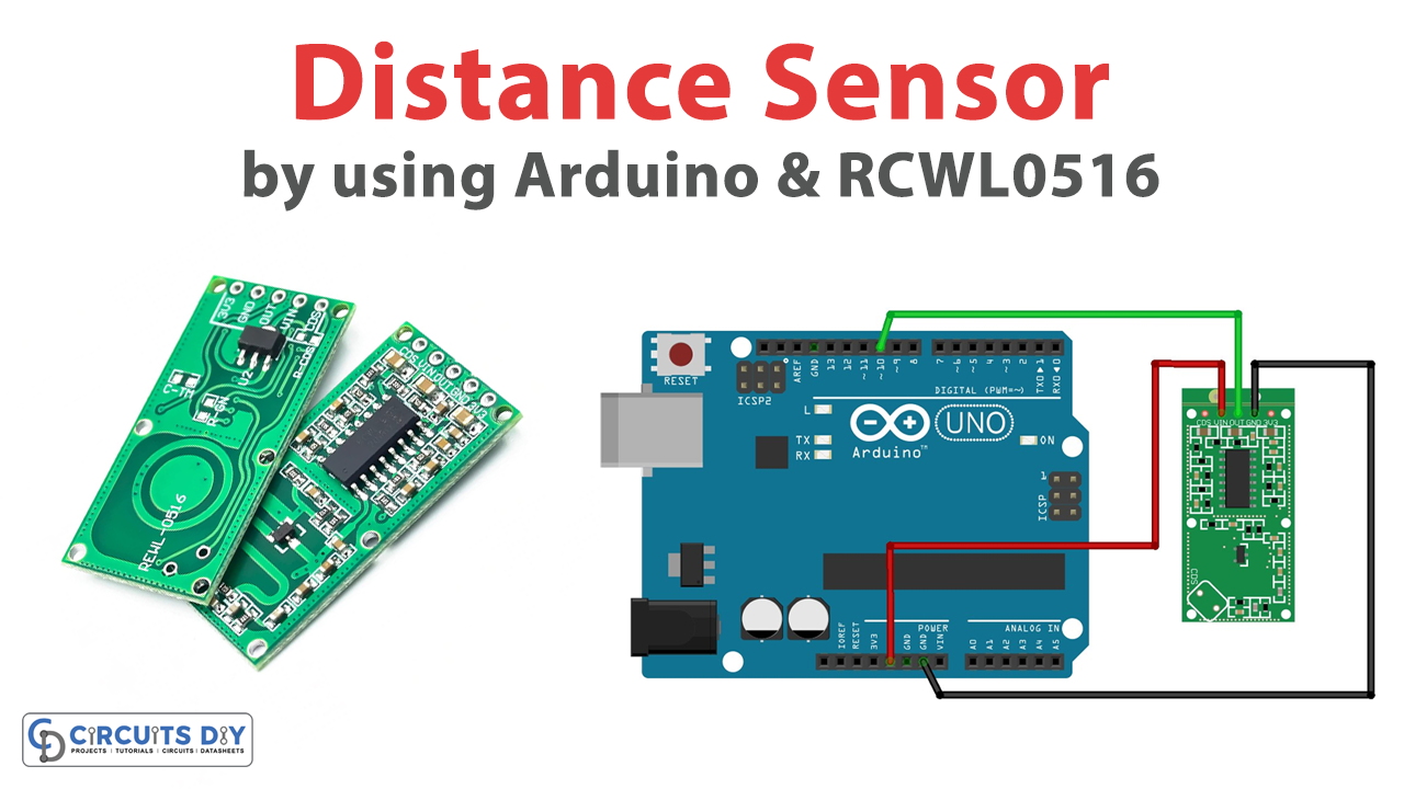
Circuit Diagram
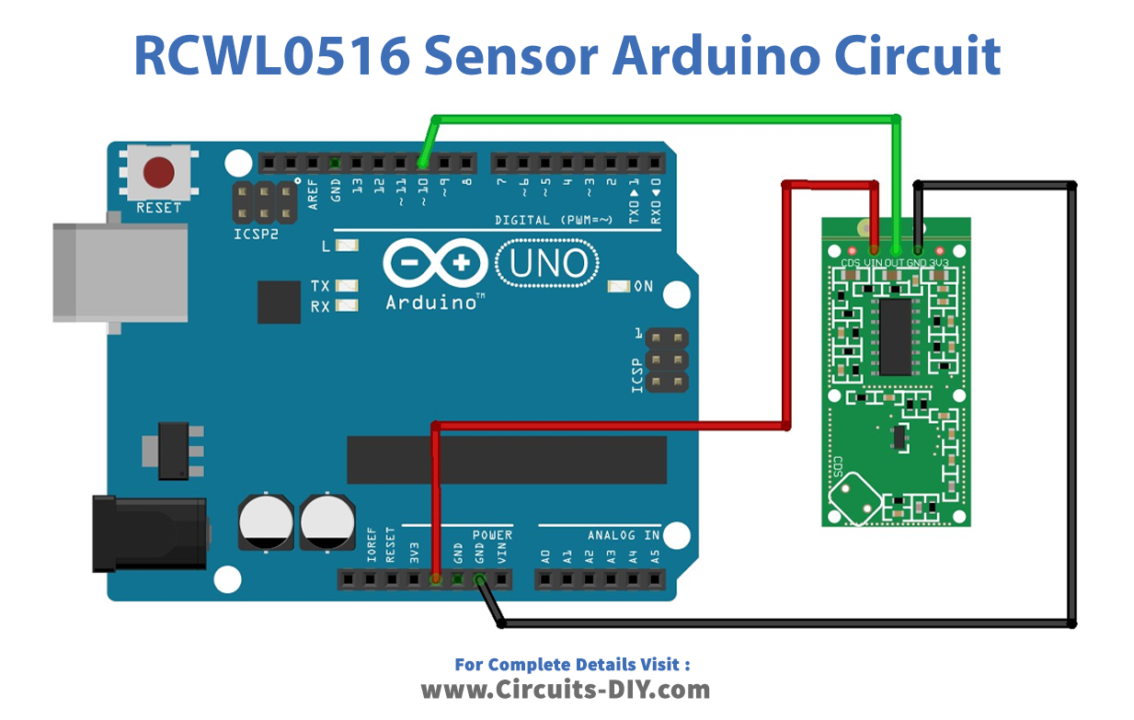
Connection Table
| Arduino UNO | RCWL0516 Module |
|---|---|
| 5V | VIN |
| GND | GND |
| D10 | OUT |
Arduino Code
int detectPin = 10;
bool detect = false;
int led = 13;
void setup() {
 Serial.begin(115200);
 Serial.println("Starting...\n");
 pinMode (detectPin, INPUT);
 pinMode (led, OUTPUT);
}

void loop() {

 detect = digitalRead(detectPin);
 if(detect == true) {
 digitalWrite(led, HIGH);
 Serial.println("Movement detected");
 }
 else {
 digitalWrite(led, LOW);
 }
 delay(1000);
}
Working Explanation
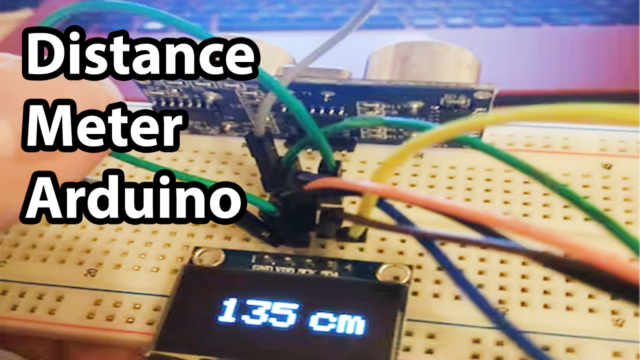
To interface the RCWL0516 Microwave Distance Sensor Module with Arduino, Upload the given code to the Arduino board to observe the results. After that, set a baud rate of 115200 and launch the Arduino IDE serial monitor. Now, the RCWL0516 microwave sensor will detect motion anytime it is in front of it and show the message “Motion detected” on the serial monitor. Additionally, the onboard LED attached to the Arduino’s D13 pin glows.
Code Explanation
- First, define the name of the Arduino pin that would store an integer. Then define the boolean object. Know that if you provide any object as the starting value of a Boolean object, including a Boolean object with a value of false, the new Boolean object does have a value of true. Then define the pin to which an LED is connected.
- In the void setup, we first give the functions to initialize the serial monitor and then shows Starting…\ on the serial monitor. Then we define detectPin (pin 10) as input and LED pin (pin 13) as output.
- In the void loop, we have made the program that if the sensors’ pin detects, the LED will glow and the serial monitor shows the message, otherwise the LED remains low. The delay is given before getting the other value.
Application and Uses
- Alarm circuits
- Security Devices
- Automation systems