The response clock or Reaction timer is a game to test how quickly you respond. This game, which we have created in this DIY tutorial, utilizes a 555 IC. The IC employs two players where the first player begins the game by squeezing the start button. When the START button is pressed,
Meanwhile, the seven-segment display starts displaying the numbers from 0 to 9 at a very high speed. When the other player stops counting by squeezing the STOP button. As the frequency of displaying numbers is high, it is troublesome and needs complete consideration to respond at the right time.
Hardware Components
The following components are required to make the Reaction Timer Game Circuit
| S.no | Component | Value | Qty |
|---|---|---|---|
| 1. | IC | NE555 timer | 1 |
| 2. | IC | CD4026 | 1 |
| 3. | Seven segment display | – | 1 |
| 4. | Push Button | – | 2 |
| 5. | Resistor | 100k, 1k, 47k | 2, 1, 1 |
| 6. | Capacitor | 1uF | 1 |
NE555 IC Pinout

For a detailed description of pinout, dimension features, and specifications download the datasheet of NE555 IC
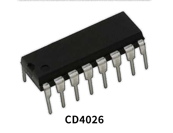
CD4026 Pinout
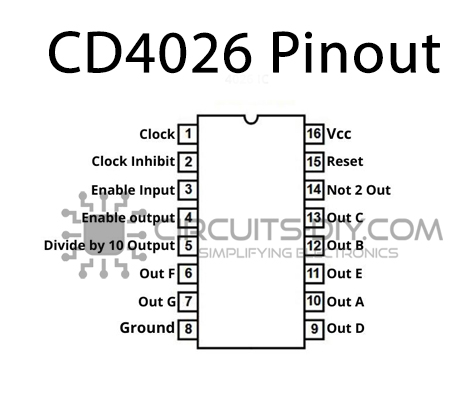
For a detailed description of pinout, dimension features, and specifications download the datasheet of CD4026
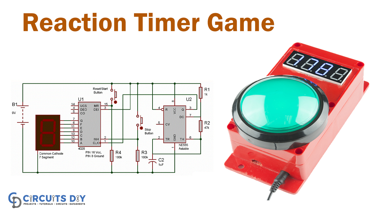
Reaction Timer Game Circuit
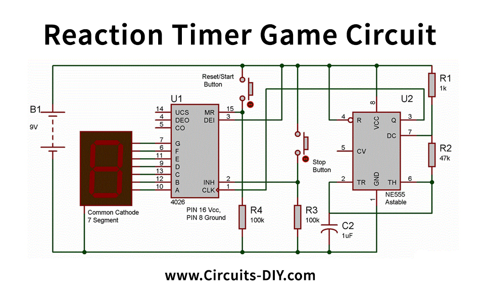
Working Explanation
Meanwhile, the 555 timer IC is a significant part of this circuit. The NE555 is utilized here to give the CLOCK pulses to 4026 IC at PIN 1 with the aim that numbers can be displayed in the seven-segment display. However, the 555 utilizes Astable multivibrator mode, and the clock pulse rate can be constrained by the Resistor R1, R2, and the Capacitor.
Moreover, here in this circuit, we have utilized around 15 pulses/second. For example, numbers are changed multiple times in a second. Although we can increase the capacitor value when we need to hinder the rate at which the numbers are continuously varying.
Applications and Uses
- Uses to generate clock pulses
- Use to check the response time of users.