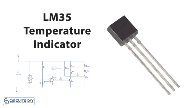
In this tutorial, we are going to make a “Simple Class D Amplifier Circuit”. The class D audio amplifier can reach an efficiency of up to 90-95%. Where the maximum efficiency of a class AB amplifier is 60-65% because they work on the active region and exhibit low power loss. If you multiply the collector-emitter voltage with the current, you can find that out. Here we design a simple class D audio amplifier circuit by using IC BD5460. It is a low-voltage drive class-D monaural speaker amplifier from a ROHM semiconductor. It can be acclimatized to low-capacity applications, such as portable audio devices.
BD5460 doesn’t crave an LC to clarify the apostle and may be an apprentice of a battery. This is a standby IC, and there is no ON/OFF clicks turn. This IC can withstand 0.8 watts into 8 ohms, an apostle in 3.6 V operating voltage. The IC has a congenital standby function, abbreviate ambit protection, thermal abeyance, and beneath voltage lockout. It requires only three external components.
Hardware Required
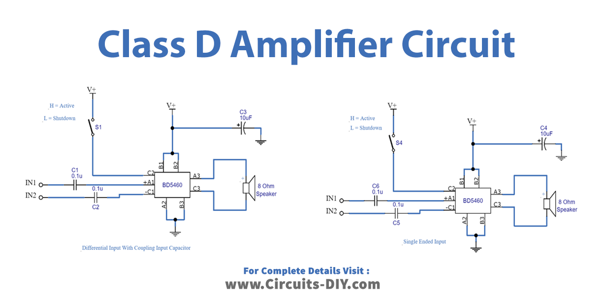
Circuit Diagram
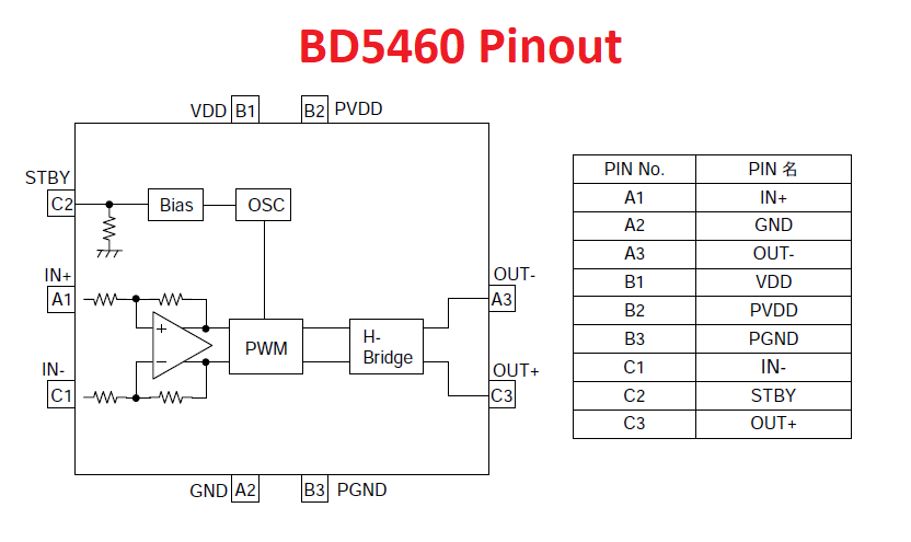
BD5460 Pinout
Features Of IC BD5460GUL
- No LC Filter is required for this amplifier
- Only three External Components Required
- Active and Shutdown option
- Gives output power of up to 2.5W
- Gain 6dB
- Analog differential input / PWM digital output with H-Bridge
- Very small package 9-Bump WL-CSP.
Working Explanation
BD5460 Amplifier can be made in two different categories, they are single-ended input and differential input with coupling input capacitors. 8 Ohm speaker gives good output with these amplifier circuits. As we can see two chic D amplifier circuits. The aboriginal one is a cogwheel ascribe chic D amplifier, while the additional one is an individual concluded ascribe chic D amplifier. The 0.1uF capacitors (C1, C2, C3, and C4) are employed as DC decoupling capacitors. The lower cut-off abundance of the amplifier depends on these capacitors. 10uF capacitors (C5 and C6) are the ability accumulation filters. S1 and S2 are the abeyance switches. Abutting the C1 pin to the top argumentation will accomplish the IC alive, and abutting the C1 pin to the arena will put the IC into abeyance mode. Audio inputs have to be connected with respect to the ground.
Applications
It is most suitable for low-power mobile audio projects.