
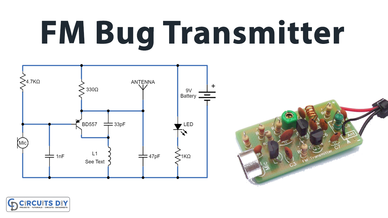
In this tutorial, we are going to make a “Small FM bug Transmitter Circuit”.
A small FM transmitter Bug is perfect for transmitting and eavesdropping purposes. Due to the high sensitivity, even the ticking of the clock to hear. We make a simple and small FM bug transmitter circuit designed by using a single transistor and a few oscillating elements, which can be constructed in small size PCB or general-purpose PCB. We can power this circuit by using a 9V battery or small voltage and package battery.
This FM bug utilizes minimum power to transmit audio signals, unlike powerful FM (frequency modulation) transmitters. In this circuit, a single-stranded wire is being used as an antenna and a condenser mic is used to fetch the audio signal. This small FM bug transmitter circuit can transmit audio signals for up to a few hundred meters. This circuit will let you spy on people. The transmitter can be placed in the desired room and the conversation heard from a place far away just using a regular FM radio set.
Hardware Components
The following components are required to make FM Bug Transmitter Circuit
| S.no | Component | Value | Qty |
|---|---|---|---|
| 1. | Transistor | BC557 | 1 |
| 2. | Resistor | 4.7KΩ, 330Ω, 1KΩ | 1,1,1 |
| 3. | Condenser Microphone | 1 | |
| 4. | Ceramic Capacitor | 1nF, 33pF, 47pF | 1,1,1 |
| 5. | Copper wire | 0.5 mm | 1 |
| 6. | Antenna | – | 1 |
| 7. | LED | – | 1 |
| 8. | Connecting Wires | – | 1 |
| 9. | Power Supply | 9V | 1 |
BC557 Pinout
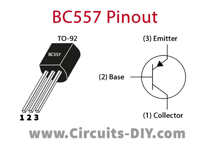
For a detailed description of pinout, dimension features, and specifications download the datasheet of BC557
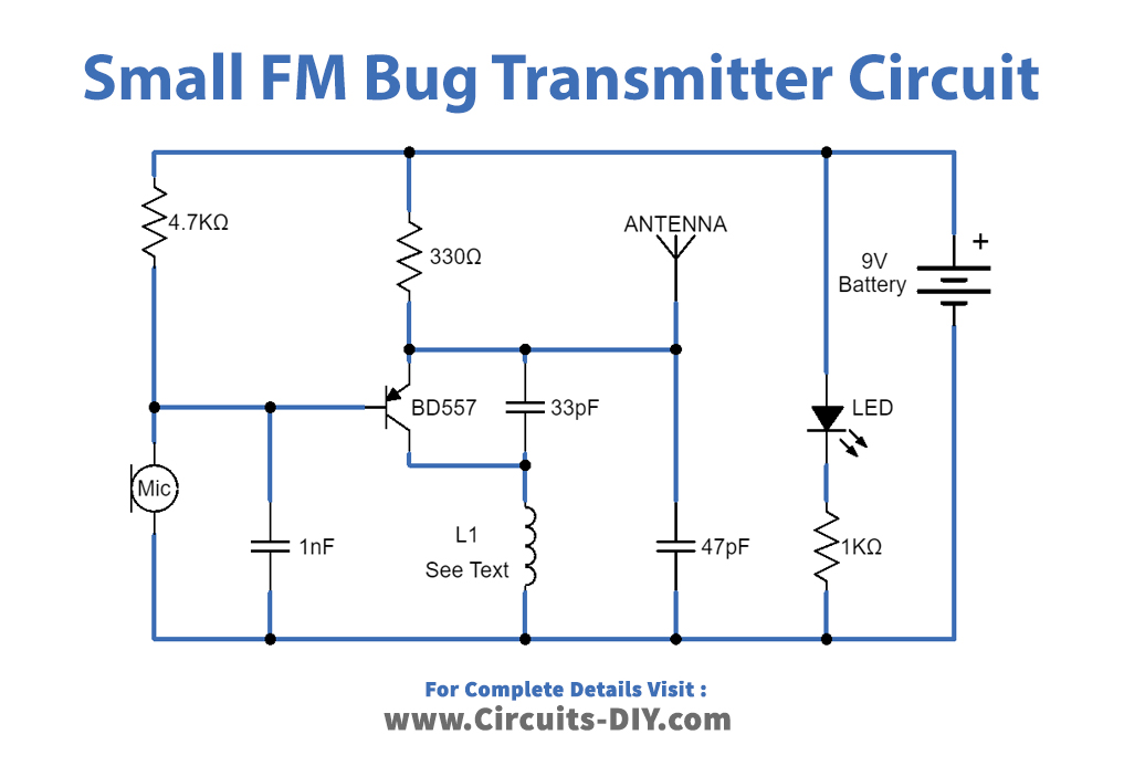
FM Bug Transmitter Circuit
Working Explanation
As we can see in the circuit, first it takes an audio input signal from condenser mic MK1. A condenser microphone has the ability to pick up low-level sound waves. Here the emitter terminal of the Q1 transistor is connected to the positive bias and antenna element. The collector terminal of Q1 is connected between the L1 and C2 components, and the signal from a microphone is applied to the Q1 transistor Base. Now, these two components L1 and C2 act as a tank circuit and oscillate carrier signal for FM. L1 can be made from 0.5 mm enameled copper wire by making 6 to 7 turns in the diameter of a normal pencil. When the sound wave is picked up by the microphone then it’s converted into an electric audio signal and then the Q1 transistor modulates that signal with a carrier signal and finally transmits the FM signal through Antenna. Here LED indicates the power supply presence.
Applications
Can be used in radio, telecommunications, computers, and other electronic applications.
Related posts:
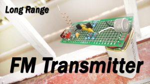 How to make Long-Range FM Transmitter Circuit-Weekend Projects
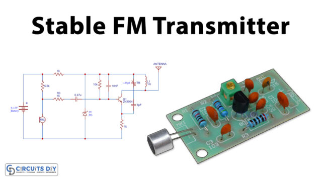 Stable FM Transmitter Project with 2N3904
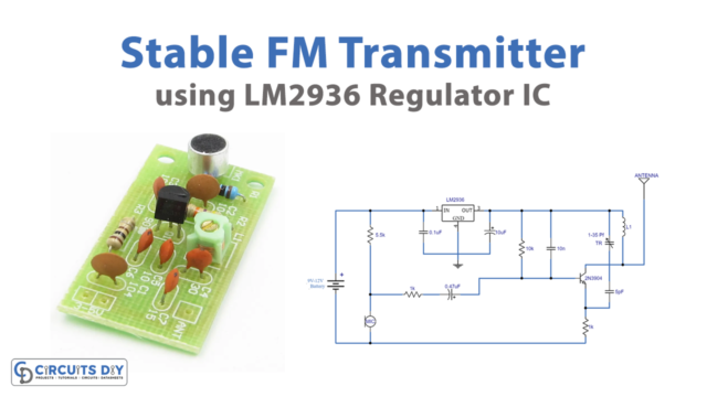 Stable FM Transmitter Using LM2936 Regulator
 FM Radio Circuit with High Reception Quality
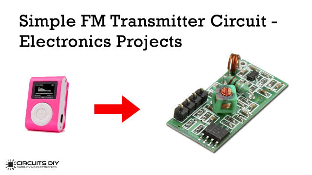 Simple FM Transmitter Circuit - Electronics Projects
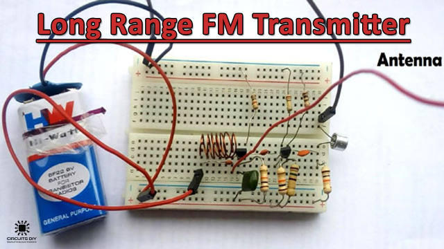 Long Range FM transmitter Circuit using 2n3904 Transistor


