Introduction
If you have ever visited any industry, you have surely perceived that industrial plants generate a lot of noise. In the same vein, traffic rails also produce a great amount of noise. Similarly, the areas that are under the construction also allow numerous machines that create noise. Likewise, in concerts, electronic instruments cause a lot of sounds. This can be harmful to the human ear and can cause hearing loss. Therefore, it is important to control the sound. So, the first step to control the noise and the sound is to measure the sound. Thus, the measurement of these sounds can be done by a Sound Pressure meter.
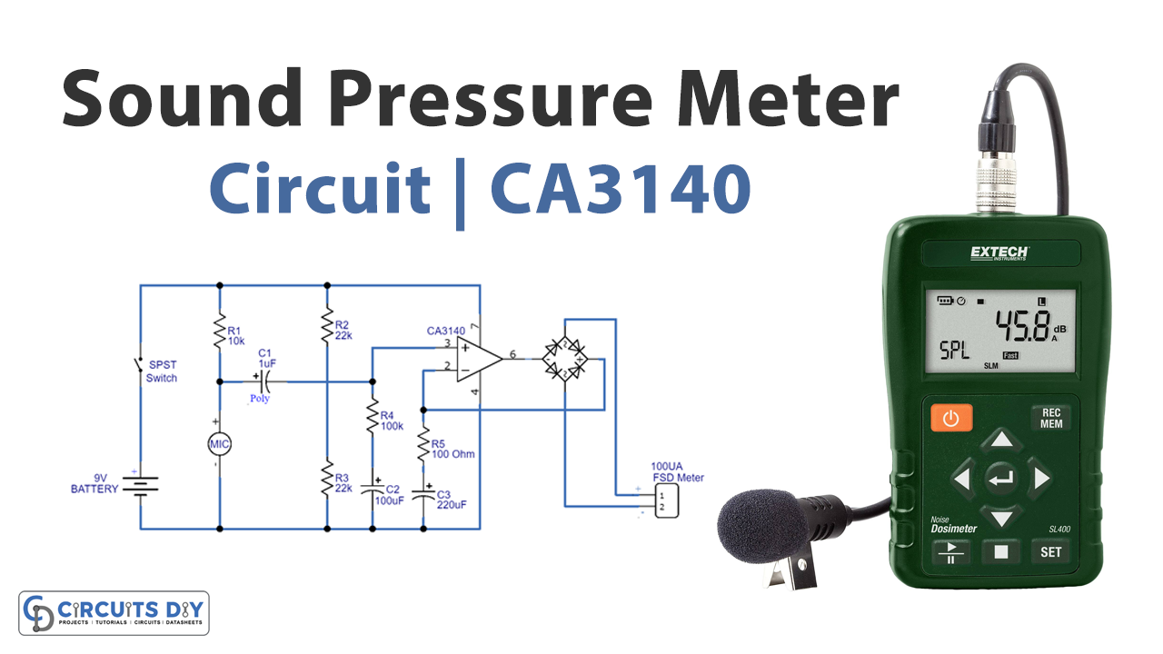
Working Principle of Sound Pressure Meter
A sound Pressure Meter contains microphones and preamplifiers. Condenser microphones are more likely to use because of their reliability and stability. This microphone in the device converts the coming noise signal into an electrical signal. But, the converted signal has a low magnitude. So, preamplifiers increase their amplitude before the signal goes toward the next stage.
Hardware Required
| S.no | Component | Value | Qty |
|---|---|---|---|
| 1. | PCB Board | – | 1 |
| 2. | Op-amp IC | CA3140 | 1 |
| 3. | Resistors | 100 ohms, 10K, 22K, 100K | 1, 1, 2, 1 |
| 4. | Capacitors | 1uF, 100uF, 220uF | 1, 1, 1 |
| 5. | Condenser mic | – | 1 |
| 6. | Diodes | 1N4007 | 4 |
| 7. | SPST switch | – | 1 |
| 8. | Battery | 9V | 1 |
| 9. | FSD Meter | 100uA | 1 |
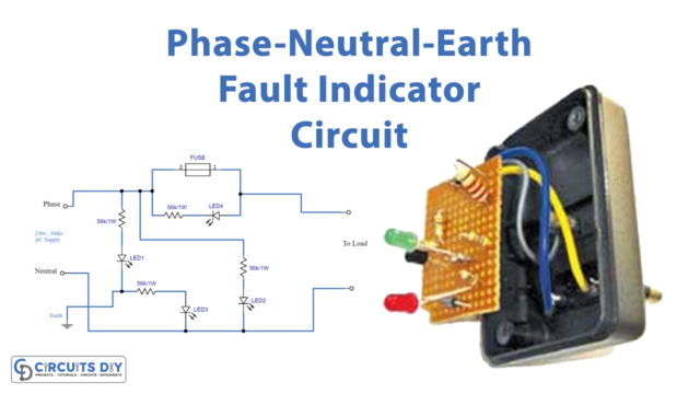
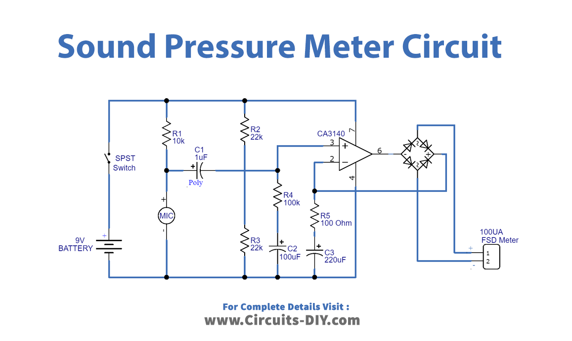
Circuit Diagram of Sound Pressure Meter
Working Explanation
When the power supply is applied to the circuit and switch will be ON. The condenser mic gives the signal to the noninverting operational amplifier wired into the circuit. After that, the bridge rectifier that is made by the diodes rectified the signal that drives the meter. As a result, the deflection on the meters is proportional to the sound coming on the condenser mic.
Application and Uses
- To measure the sound and noise.
- In sound-controlling devices.
- Noise monitoring stations.
- In smartphone applications.