A flip-flop is an electronic circuit with two stable states that can store binary data. You can change the stored data by applying a variety of inputs.
A T flip flop is just like JK flip-flop. These are a single input version of JK flip flop. You can get the changed form of JK flip flop by connecting both inputs J and K. This flip-flop has only one input along with the clock input.
We call these flip-flops as T flip-flops because of their ability to complement its state (i.e.) Toggle, hence the name Toggle flip-flop.
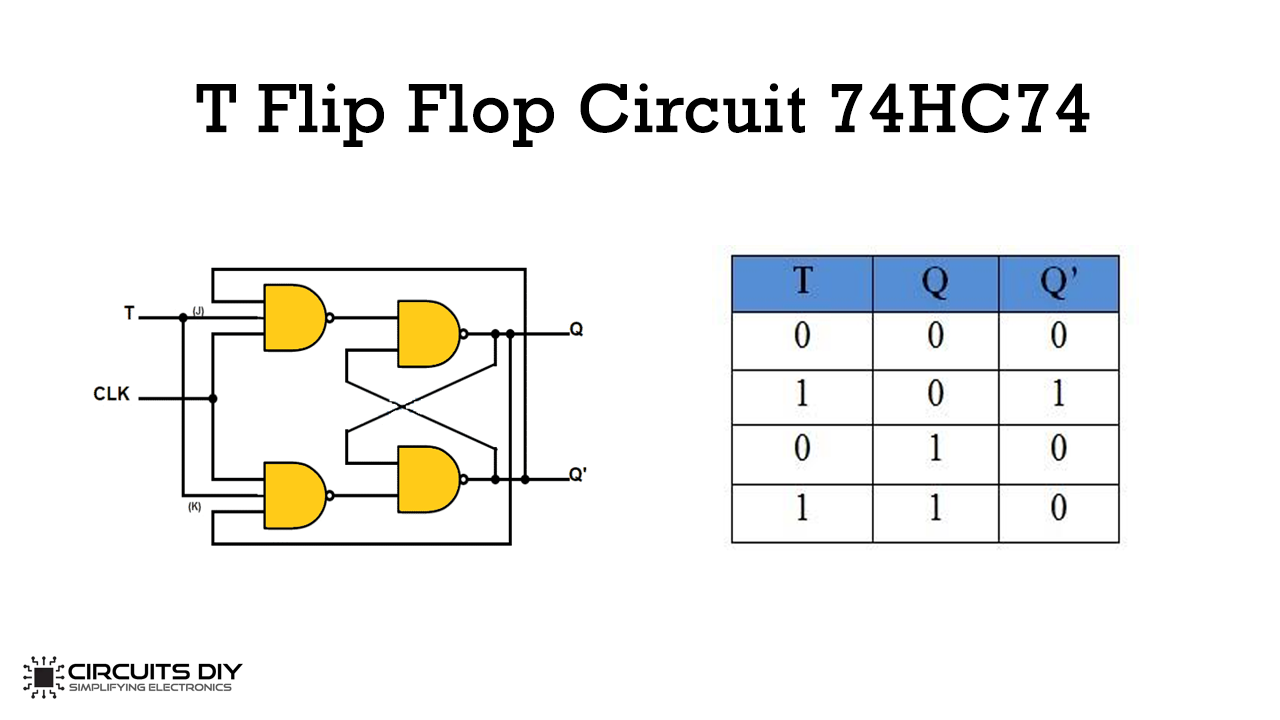
Truth Table of T Flip Flop
| T | Q | Q (t+1) |
| 0 | 0 | 0 |
| 1 | 0 | 1 |
| 0 | 1 | 1 |
| 1 | 1 | 0 |
Hardware Components
| S.no | Component | Value | Qty |
|---|---|---|---|
| 1. | (Dual D flip-flop) | 74HC74 | 1 |
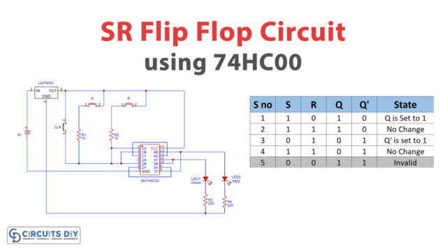
| 2. | 5v Voltage Regulator | LM7805 | 1 |
| 3. | Tactile Switch | – | 4 |
| 4. | Battery | 9V | 1 |
| 5. | LED (Green, Red) | 5mm | 2 |
| 6. | Resistors | 1k,220k | 4,2 |
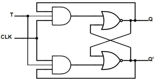
T Flip-flop Circuit Diagram
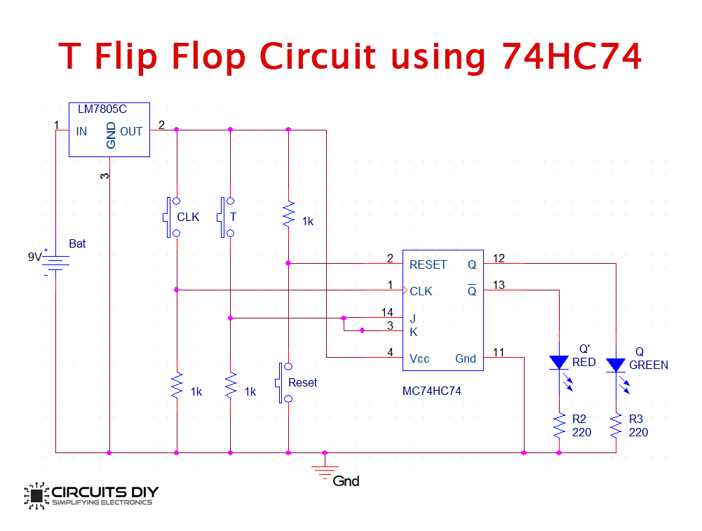
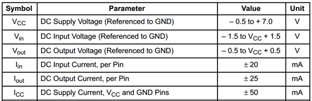
The IC power source VDD ranges from 0 + 7V and data provided in the datasheet. The following snapshot shows it. Also, we have used LED on the output; it has limited the source to 5V to control the supply voltage and DC output voltage. We have used the LM7805 regulator to limit the LED voltage.
Applications of Flip-Flops
These are different flip-flops used in digital electronic circuits. Below are the applications of Flip-flops:
- Counters
- Frequency dividers
- Shift registers
- Storage registers