Introduction
Darkness scares most of us, and who knows, maybe that was the reason that light got invented. But, today our topic is not about light but the dark. The darkness detector sensor. But, the question arises where do we need a detector that senses dark? See, we humans are trying every day to get an automated world, we love to don’t spend our time on various little things that distract us from doing other great work. For instance, take the example of street lights, to turn on those lights manually, requires someone to do that duty every single day. But, on the other hand, if we make this automated by using a dark sensor so that it detected the darkness and turns on automatically, this would save us time. So, In this tutorial, we are going to make “Dark Detector Circuits using different Light Sensors”
Hardware Required
| S.no | Component | Value | Qty |
|---|---|---|---|
| 1. | LDR | – | 1 |
| 2. | Battery | 6V | 1 |
| 3. | Buzzer | – | 1 |
| 4. | NPN Transistor | BC547 | 1 |
| 5. | Variable Resistor | 100KΩ | 1 |
| 6. | Resistor | 300Ω | 1 |
Circuit Diagram
Working Explanation
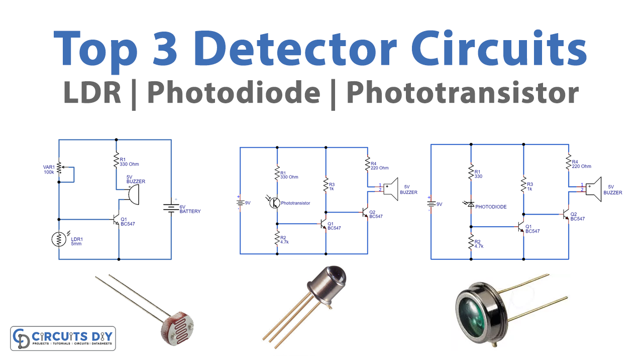
Since this article is about discussing different dark Detector Circuits using different Light Sensors, we will discuss them all one by one.
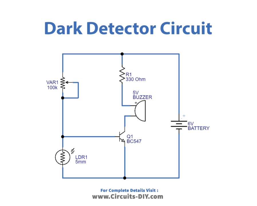
Dark Detector Using LDR
First look at the fig1, there is a variable resistor in the circuit through which we can change the sensitivity. When there is a constant light falling on the LDR, there is no current flow through the circuit. Whenever something occurs between the light and LDR, the LDR detects the darkness and decreases its resistance. In that case, the current starts flowing through the circuit. As a result, the buzzer beeps.
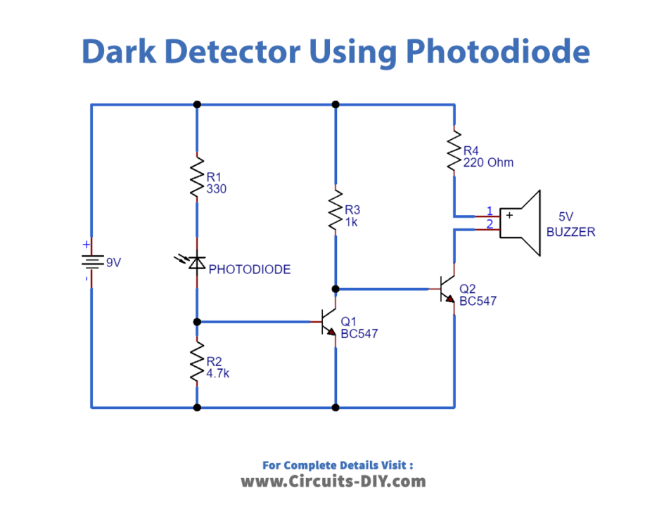
Dark Detector Using Photodiode
Now, look at fig 2, here we are using a photodiode. The working of this circuit is the same as the above circuit. Whenever something comes between the light and the photodiode, it detects the darkness and decreases its resistance. In that case, the current starts flowing through the circuit. As a result, the buzzer beeps. The only difference in the circuits is the components. Fig 1 circuit uses LDR while fig 3 uses photodiode. Thus, there is a difference between both them. LDR has a long response time, thus it takes several seconds to change conductivity after exposure to light. On the other hand, Photodiode provides instant response.
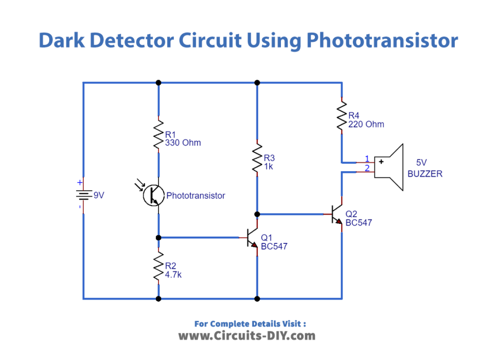
Darkness Detector Using Photo Transistor
Now, take a look at fig 3, here we are using a phototransistor. So, when the phototransistor is exposed to darkness the buzzer starts buzzer. We can adjust the sensitivity of this circuit by changing the values of resistors R1 and R2.
Application and Uses
- Automatic street lights.
- Burglar alarm circuits
- Intruder alarms.
- Night lights and lamps, etc