In this tutorial, we are making a project on a Temperature alarm circuit. This circuit activates a buzzer alarm when it receives or senses heat, therefore you can also call this circuit a heat alarm circuit. This is one of the simplest and most inexpensive circuits as it is only using 5 components. A thermistor is used to detect heat. Thermistors are devices that have the highest resistance when the heat is low and its resistance decreases as the heat increases and then the current can pass through it.
For the sensitivity of this circuit two BC547, and NPN transistors are connected to form a Darlington pair. A buzzer is used to act as an alarm, the voltage of the buzzer should be the same as the input voltage. To adjust the level of heat at which you want your alarm to activate we have used a variable resistor.

Hardware Components
The following components are required to make Temperature Alarm Circuit
| S.no | Component | Value | Quantity |
|---|---|---|---|
| 1. | Battery | 9V | 1 |
| 2. | Thermistor | – | 1 |
| 3. | Buzzer | 9V | 1 |
| 4. | Transistor | BC547 | 2 |
| 5. | Variable resistor | 12K | 1 |
BC547 Pinout

For a detailed description of pinout, dimension features, and specifications download the datasheet of BC547
Temperature Alarm Circuit
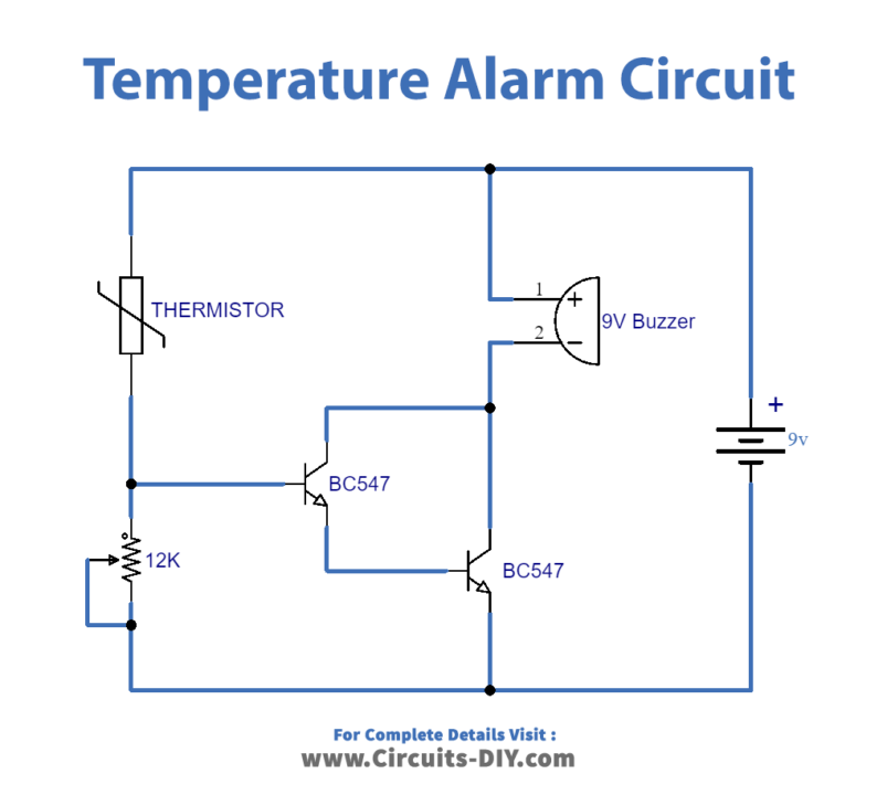
Working Explanation
The working of this circuit is very simple to understand. Initially in the absence of heat, the circuit remains off. When the thermistor receives heat its resistance is decreased and it allows the current to pass through it. Now the transistors will receive their required voltage and activate which activates the buzzer and in this way, you will be notified when the heat is present.
This circuit can be operated on a 9V battery, adaptor, or transformer.
Applications and Uses
This circuit is compact and can be easily fitted anywhere. It has applications in those devices or equipment that you don’t want to get overheated.