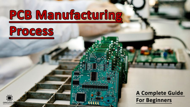
PCBA stands for printed circuit board assembly, and it means mounting the electronic different components, like capacitors, resistors, ICs, and many other electronic components on the board. The type of devices mounted on the board depends on the type of device you are preparing the board for. Hence, the boards vary from mobile phones to microwave ovens, cars, and laptops.
Read on to know more about FS PCBA and its manufacturing process.
Types of PCBA technologies
There are two types of PCBA technologies:
- 1. SMT
SMT stands for surface-mount technology, and in this, the electronic components will directly get mounted on the surface of the printed circuit board. For electronic components, like transistors that go onto the circuit board, SMT is the suitable option for assembling such tiny and tiny components.
It would help you save space because no drilling would be required, and it will also speed up the production process. With the help of SMT, all the components on the board will fit, and both sides of the board will get utilized.
- 2. THT
There is another method thru-hole technology that people used before when SMT technology was introduced. The electronic components are plugged into the circuit board through holes. For using this technique, manufacturers have to solder the extra part of the wire on the board. It takes more time than SMT, and it has advantages compared to SMT.
One of the advantages of THT is that through thru-hole technology, the electronic components will be strongly attached to the board. This technology is more suitable for electronic components that are larger in sizes, such as capacitors and coils. They can withstand high voltage, high power, and mechanical stress.
PCBA Manufacturing- Step-By-Step Process
If you don’t have much idea about how the PCBA process works, let’s talk about it in a little detail:
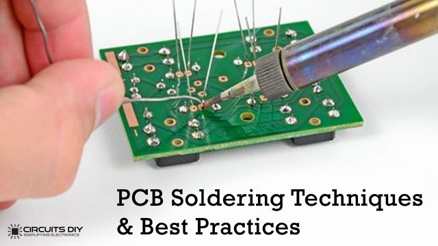
- Solder paste
First of all, you will have to use the solder paste on the circuit board at specific points, and that solder-pasted area would hold special electronic components. The solder paste is a mixture of basically different tiny balls.
One of the most used materials in solder paste is tin, and the amount of tin in the paste is approximately 96.5%. Other than tin, silver and copper are present with 3% and 0.5% quantity.
After mixing all the materials with the help of flux, it helps in melting the material and bonding to the circuit board surface. The solder paste has to be pasted on the circuit board at specific points in the right amount of quantity. Different applicators would be used to apply this solder paste to different locations on the circuit board.
- Place the components
After you are done with the solder paste process, now it is time to pick up the electronic components that you need to paste on the circuit board. Both automated and traditional methods can be used to pick and place the components on the board.
If the manufacturer goes for the traditional method, they would use tweezers to place the components. If an automated technique has been used, the machine will place the components on the board.
- Solidify soldering
Once you have placed all the components on the circuit board, the next step would be soldering them with solder paste. This process would get completed with the reflow process. The process consists of sending the board to the conveyor belt. In the conveyor belt, the board will pass through the reflow oven, which simply resembles a pizza oven.
The oven has heaters with different temperatures, and they will heat the board at different temperatures to transform solder into solder paste. Once the healing process is done in the same conveyor belt, the board will go through the cooling process too, and it will solidify the paste.
- Manual/automatic inspection
After solidifying the board, the next process is to check the quality of the board and whether it has been manufactured perfectly or not.
Sometimes, the board comes out of the conveyor belt, and the connections on the board are a bit loose. So, there are two methods of inspecting the board.
- Automatic inspection
It is one of the finest ways of inspecting the quality of the board because an AOI machine will inspect the PCBA board with plenty of high-resolution and highly powered cameras.
Those cameras will cover the board from every angle to check whether the board has been manufactured perfectly or needs some kind of retouches.
- Manual inspection
Doubtlessly, in this world where technology has been doing great in inspecting the PCBA board, but still manual inspection technique is still very much popular. It would work for PCBA on a smaller scale, but it won’t work on a larger scale.
The person doing this inspection might get tired of looking at the small components for a longer period of time.
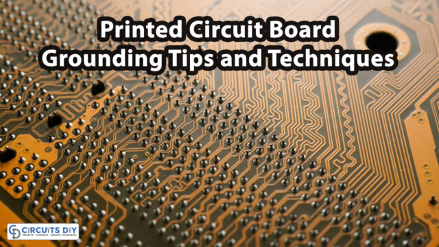
- Through-hole technology
The type of technology for mounting electronic components on the circuit board depends on the type of board you are going to manufacture. There will be holes on the circuit board through which you will mount components on the circuit board.
Once the components are mounted, they will go through the manual soldering process. One person will insert one component, and then, it will go to the next person for the next component. This is how the manual soldering process goes on. After that, the board goes through the oven that contains molter solder. It will wash the circuit board, and it won’t work for double-sided circuit boards.
The last step would be the inspection of the board. In which, the tester will test the board on different voltages, currents, and signals. If the board shows any type of fluctuation, it means the board failed the test. If the board gets rejected, it will recycle or scrape the board.
The Final Thoughts:
We have talked about the PCBA boards and how professionals prepare them according to the type of device in which it is going to get installed. The type of process that would be used to make the board also depends on the type of device and the electronic components that would be installed on the board.