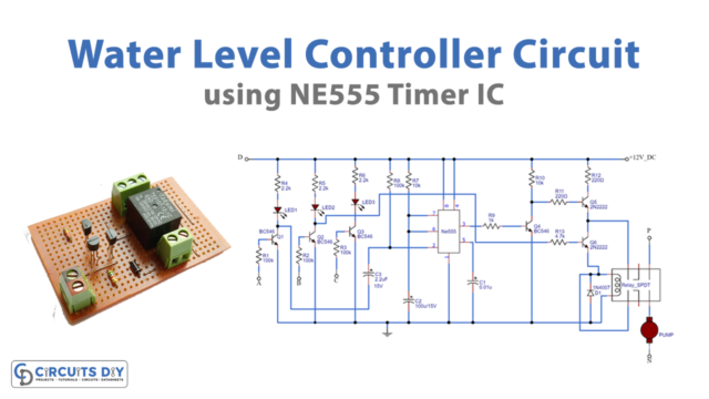
This is a water pump controller circuit. This circuit works between 8 levels/Height of water container. In this case, the circuit contains two ICs, the timer IC NE555 and the 8-transistor Darlington pair IC ULN2803. Furthermore, a relay circuit attached powers up or shuts down the motor, accordingly.
Hardware Required
| S.no | Component | Value | Qty |
|---|---|---|---|
| 1. | DC Battery | 12V | 1 |
| 2. | PNP Transistor | 2N3906 | 3 |
| 3. | Relay | 12V | 1 |
| 4. | Probe | – | 9 |
| 5. | IC | NE555 Timer | 1 |
| 6. | IC | ULN2803 | 1 |
| 7. | Diode | 1N4007 | 1 |
| 8. | Resistor | 470Ω,1KΩ,10KΩ,1MΩ | 10, 2, 8, 2 |
| 9. | LEDs | – | 10 |
| 10. | Water Pump Motor | – | 1 |
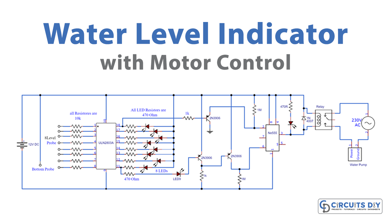
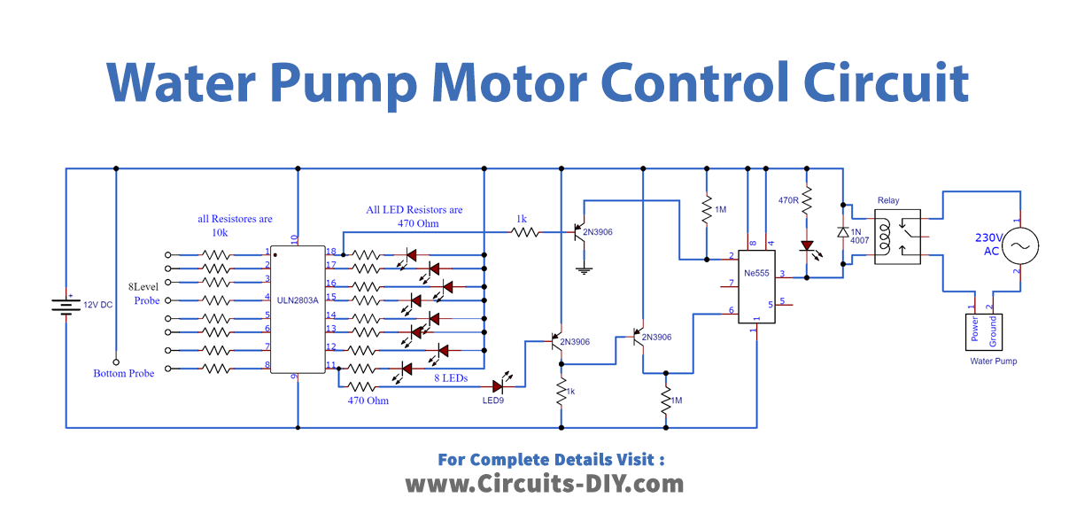
Circuit Diagram
Circuit Explanation
The first part of the circuit detects the level of water using IC ULN2803. Firstly, a positive rail is attached at the bottom of the container as the bottom probe. Whereas, the 8-level probes are inserted at different levels/heights of the container to be measured. Also, each of the 8 probes links the base of transistors in the IC from PIN01 to PIN08. After that, the LEDs are attached to IC PIN 11 to PIN 18 along with its current limiting resistors of 470Ω. Secondly, the circuit starts working as soon as the 12V battery is connected.
The working is such that the electrical connection is set up between the bottom probe and one of the 8-level probes. The water level reaches a certain level of the probe; hence, the corresponding probe connects with the bottom probe. Therefore, the LED, associated with the probe and transistor, lights up.
After that, the second part of the circuit takes up the signal from IC and accordingly, turns the relay/motor ON/OFF. In this case, the first-level probe and last-level probe corresponding outputs are taken as the input signals. Furthermore, these input signals are first amplified by a 2N3906 PNP transistor and then sent to IC NE555. The timer IC outputs a regular interval signal to the relay.
With the level 1 probe or PIN 11 of the IC HIGH, the motor has to start. Similarly, for the water level is full, the PIN 18 of IC outputs HIGH. Timer IC receiving a signal from probe 1, turns OFF the relay, thus turning the motor OFF. Whereas, timer IC, receiving a signal from probe 8, triggers the relay thus starting the water pump motor.
Application
Automated water pumps motor starter.